Nov 18, 2026
Is IP68 truly waterproof?
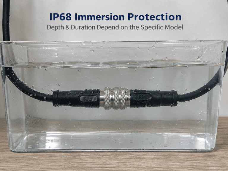
IP68 waterproof connectors are conditionally protected, not immune to water in every situation. When I discuss connector selection…


M12 connectors are not universal, although compatible interfaces may mate across brands. When I handle a replacement inquiry, I know that a matching name or pin count can hide important differences. I separate the decision into three questions: Will it mate, will it work, and will it serve as a drop-in replacement?
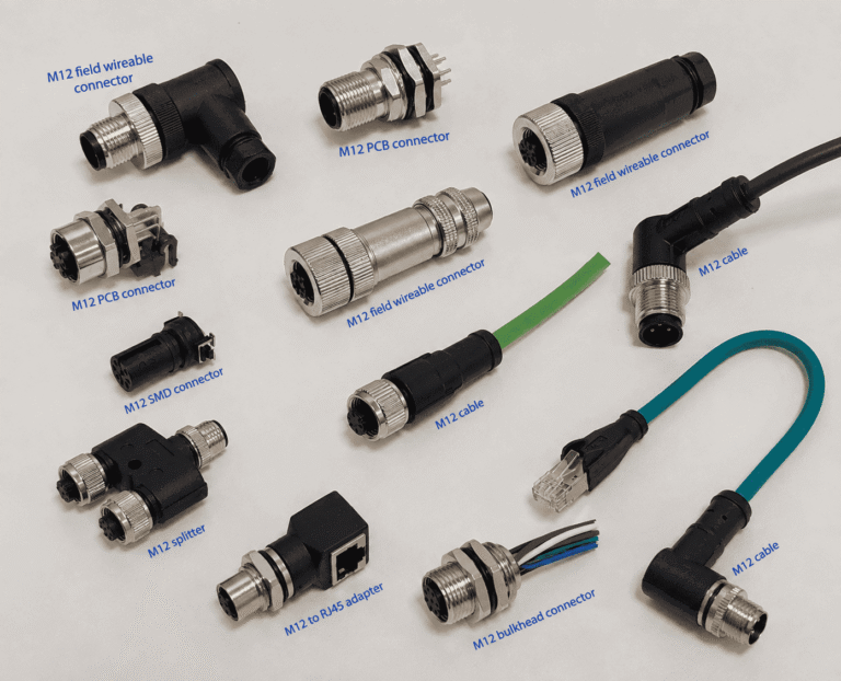
M12 connectors belong to a family of standardized interfaces, but the M12 designation alone does not establish interchangeability. I evaluate the mating interface, electrical functions, and installation requirements separately. A replacement must satisfy all three, including the operating conditions, before I recommend that a buyer confirm a sample.
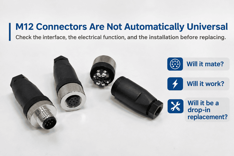
A typical inquiry gives me a useful starting point: “I need to replace a four-pin M12 connector.” I first clarify whether the buyer means a complete cable, a field-wireable plug, or a panel receptacle—and which existing end will remain in place.
When I receive an inquiry that says only “M12, four pins,” I still lack the information needed to select a replacement. The description sounds specific, but several interfaces and constructions can sit behind it. I begin by identifying exactly which mating interface the original part uses.
For a common threaded interface, I read M12×11 as a nominal 12 mm mating thread with a 1 mm pitch. Applicable IEC specifications define requirements for particular interfaces. I do not treat that designation as evidence of the rear mounting thread, device pin functions, or every product’s electrical ratings.
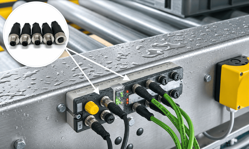
I use the IEC 61076-2 series as the standards reference for relevant circular connector interfaces. IEC 61076-2-1012 is a relevant reference for common screw-locking M12 connectors, but I still check the standard designation and edition declared for the particular product.
That distinction matters because standardization applies within a defined scope. I do not assume that every connector marketed as M12 follows the same interface specification or uses the same locking arrangement.
When I compare drawings, I look for the features that define the proposed mating pair:
I then examine the remaining product specifications separately. The interface designation does not tell me the conductor size, cable jacket material, rear termination arrangement, or permitted installation conditions.
A panel receptacle can have one thread at its front mating interface and another thread where its body attaches to equipment. Those threads perform different jobs.
For example, M12×1 at the mating end does not establish the size of the panel mounting hole. I need the dimensioned drawing to identify the rear mounting thread and its associated hardware.
I also avoid treating a shared interface as a shared rating. Two products can present compatible mating geometry while carrying different published current, voltage, temperature, or environmental specifications.
For the four-pin replacement inquiry, my first useful result is therefore a complete interface description. I want more than “M12”: I want the specified coding, contact arrangement, locking construction, and identity of the connector that will remain installed.
When a buyer asks whether another brand will fit, I do not use the brand name as my deciding factor. A familiar logo can create false confidence, while an unfamiliar supplier may offer a suitable interface. I compare the two specific parts and their drawings.
I treat cross-brand M12 connectors as potential mating candidates4 when their coding, contact arrangement, complementary pin/socket contacts, and locking geometry agree. Matching descriptions support further evaluation; they do not prove compatibility. I check the precise pair against manufacturer drawings and confirm the proposed combination with a sample.
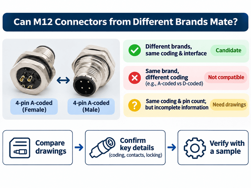
Suppose the original connection uses a four-pin A-coded interface. A replacement from another brand may be a candidate if it has the corresponding four-pin A-coded interface, complementary contacts, and a compatible coupling arrangement.
I still need the actual part numbers. One manufacturer may offer several products that appear similar in a catalog but differ in construction or intended counterpart.
I also distinguish contact sex from external appearance. I check whether the contacts are pins or sockets instead of relying only on the connector shell or a loosely written product title.
The reverse situation also matters. Two M12 connectors from the same brand may not mate. A four-pin A-coded end and a four-pin D-coded end have different keying5. Their shared brand and contact count do not make them a mating pair.
| Comparison | My interpretation |
|---|---|
| Different brands, corresponding four-pin A-coded interfaces, complementary contacts, compatible locking geometry | I have a candidate pair that needs drawing and sample confirmation. |
| Same brand, four-pin A-coded end versus four-pin D-coded end | I reject the pairing because the coding differs. |
| Same coding and contact count, incomplete coupling information | I request the missing drawings before recommending a replacement. |
I ask for a straight-on photograph of the mating face, with the contacts and coding keys clearly visible. For a comparison image, I want both photographs presented in the same orientation.
An angled photograph can hide the key position or make the contact arrangement difficult to interpret. A rear wiring view can also mislead a comparison because its orientation differs from the mating-face view.
I use photographs to identify visible features, then resolve dimensions and construction details through specifications. A photograph cannot establish dimensional tolerances, internal wiring, material specifications, or the manufacturer’s declared compliance.
For the running four-pin inquiry, I can now narrow the question: “Does this proposed end match the particular interface that stays on the machine?” That decision comes before any claim about electrical operation.
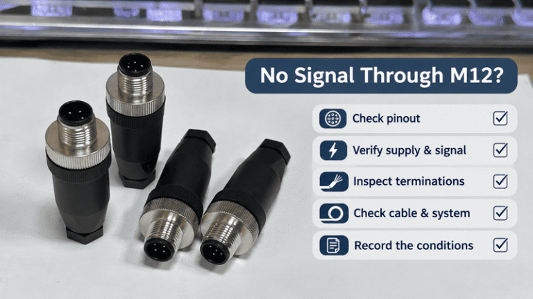
A connector that screws into place can look like a successful replacement. I still need to know what each contact does. If I overlook the device pinout or cable wiring, I may recommend an assembly that connects mechanically but cannot carry the required power, signals, or data.
I compare three separate records: the device port’s pin functions, the cable’s end-to-end pin-number mapping, and the contacts that are actually wired. I then check the relevant electrical and transmission specifications. I never use wire color alone6 to establish that two assemblies perform the same function.
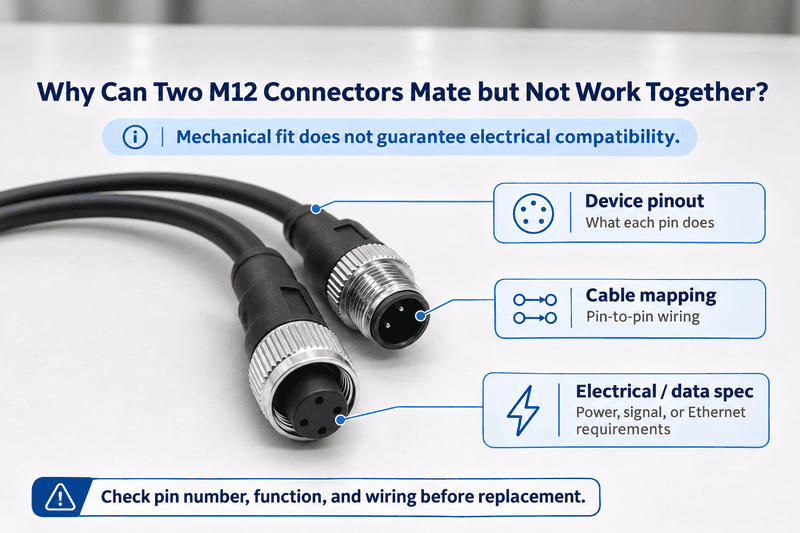
For the four-pin replacement inquiry, I ask for the device connection diagram before interpreting the cable.
The device documentation tells me the intended function of each numbered contact. The cable documentation tells me how those contacts connect to the other end. Those documents answer different questions, so I do not substitute one for the other.
I compare the information in this order:
| Information | What I establish |
|---|---|
| Device port pinout | I identify the function assigned to each numbered contact. |
| Cable wiring diagram | I identify where each contact connects at the opposite end. |
| Populated-contact information | I confirm which contact positions have an actual electrical connection. |
| Electrical and transmission specifications | I assess whether the assembly supports the required service. |
A contact position shown in a connector drawing does not, by itself, prove that a complete cable assembly wires that position through7. I need the assembly’s wiring information.
I also avoid interpreting conductor colors as universal pin assignments. I use the supplier’s documented relationship between pin number, conductor, and function.
For a power connection, I compare the published voltage and current ratings with the application requirements. I also check the conditions attached to those ratings, including conductor size and relevant temperature limitations8.
For a data connection, I need more than electrical continuity. I check the intended communication system, cable construction, pair arrangement where applicable, and shielding requirements. I ask a qualified engineer to assess application-specific suitability when the available documents do not settle the question.
An IO-Link example shows why this distinction matters. For an IO-Link Class B port, pins 2 and 5 serve the additional power supply connection9. If a device requires that auxiliary supply, a mechanically compatible cable that does not connect those positions cannot provide it.
I check the current IO-Link Interface and System Specification and the particular device manual before using that example in a purchase specification. I do not extend it to every IO-Link device or every M12 connection.
For my original four-pin inquiry, this also creates a useful pause: if the device documentation requires a fifth contact, I need to resolve the mismatch in the buyer’s description before selecting a replacement.
Even after I establish mating and electrical compatibility, installation can stop the replacement. A different mounting thread, cable outlet, or termination arrangement can require changes to the equipment. I therefore reserve “drop-in replacement” for a part that also fits the existing installation and operating requirements.
I consider M12 connectors drop-in replacements only when the proposed parts satisfy the mating, electrical, mechanical, and environmental requirements of the original installation. I check both ends of a cable, the termination limits of a field-wireable plug, or the mounting and rear connection details of a panel receptacle.
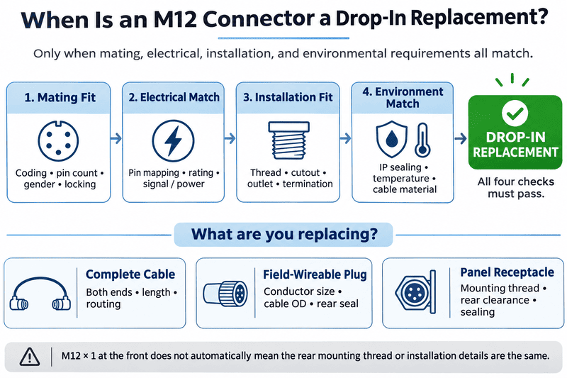
The phrase “replace the connector” can describe three different purchases. I clarify that point before comparing dimensions or preparing a quotation.
| Part being replaced | Checks after confirming mating |
|---|---|
| Complete cable | I check both end connectors, pin mapping, exit direction, cable specification, and shielding. |
| Field-wireable plug | I check the termination method, conductor size, cable outside diameter, and rear-seal fit. |
| Panel receptacle | I check front/rear mounting, cutout, mounting thread, PCB footprint or rear clearance, and installed sealing conditions. |
For a complete cable, I also check length and routing. A straight outlet and an angled outlet can create different clearance requirements near a machine frame or enclosure.
For a field-wireable plug, I compare the existing cable with the permitted conductor and cable-diameter ranges. A compatible front interface does not establish that the original cable will fit the replacement’s termination and sealing system.
For a panel receptacle, I need the installation drawing. I check the mounting direction, panel thickness limits, hardware, sealing arrangement, and space behind the panel.
A front M12×1 mating interface and a rear M16×1.5 mounting thread can appear on the same product. The first designation describes the connection to the mating connector. The second describes a different mechanical attachment.
If two receptacles use different rear mounting threads, I cannot call them drop-in replacements merely because their front interfaces mate with the same cable. The existing panel cutout and mounting hardware must suit the proposed replacement.
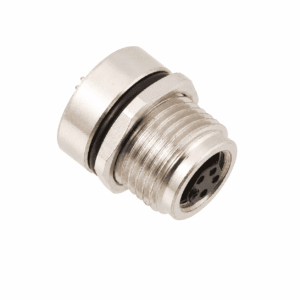
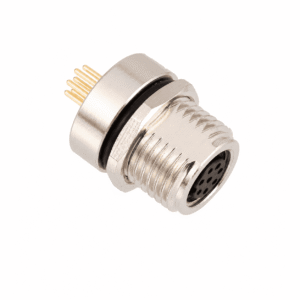
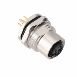
For a NITAI product comparison, I would select two verified samples and photograph them with separate labels for the front mating thread and rear mounting thread. I would support those labels with their individual drawings. I would not infer their pinouts or PCB footprints from a product-family page.
I read an ingress-protection rating together with the manufacturer’s stated conditions10. I check whether the rating applies when correctly mated, when a specified cap is installed, or under another documented arrangement.
I also review the relevant temperature range, cable material, movement requirements, and exposure conditions. Where certification documents matter to the purchase, I request documents that identify the applicable product and scope.
I recommend qualified engineering evaluation for application-specific decisions. My role in supplier selection is to organize the evidence and identify unresolved differences before the buyer commits to volume.
I do not treat pin count as proof of interchangeability. Two four-pin connectors can differ in coding, contact construction, locking geometry, wiring, and ratings. I first establish whether their interfaces can mate, then check electrical functions and installation requirements separately.
I consider another supplier’s cable when its documented interfaces, wiring, cable construction, and ratings meet the application requirements. I compare both ends and the complete assembly drawing. I also confirm a sample before a bulk order, especially when the existing installation leaves little mechanical clearance.
I use a clear photograph to help identify coding, contact arrangement, and visible construction. I cannot establish internal wiring, exact dimensions, PCB footprint, or sealing performance from appearance alone. I request the original part number, a dimensioned drawing, and the device pinout to complete the comparison.
I do not treat a shared IP rating as a guarantee of identical installed performance. I check each manufacturer’s stated conditions, including mating, panel sealing, cable diameter, and assembly instructions. I ask for professional evaluation when the operating environment creates requirements that the published documents do not resolve.
I evaluate M12 connectors through one ordering sequence:
For a NITAI replacement inquiry, send those details so I can help narrow the selection.
Publication source note: Live source verification was unavailable for this draft. Before publication, the IEC and IO-Link statements should be checked against their current source documents. The proposed Phoenix Contact 1551820/1419768 comparison is omitted because their current drawings were not verified. No NITAI product-family listing is used as proof of wiring, PCB dimensions, or sealing performance.
"ISO metric screw thread", https://en.wikipedia.org/wiki/ISO_metric_screw_thread. Metric thread designations use M12 for a nominal diameter of 12 mm and ×1 for a pitch of 1 mm; this designation alone does not specify the connector's other dimensions. Evidence role: definition; source type: institution. Supports: The meaning of the nominal diameter and pitch in an M12×1 metric thread designation.. Scope note: The thread definition does not establish that a particular product conforms to an M12 connector interface standard. ↩
"IEC metric screw sized connectors", https://en.wikipedia.org/wiki/IEC_metric_screw_sized_connectors. IEC 61076-2-101 specifies requirements for the circular connectors within its stated scope, including screw-locking M12 interfaces; its scope does not establish compliance for every product sold as M12. Evidence role: definition; source type: institution. Supports: The published scope of IEC 61076-2-101 and the interfaces it covers.. Scope note: The applicable edition and a specific product's declared conformity require separate verification. ↩
"IEC metric screw sized connectors", https://en.wikipedia.org/wiki/IEC_metric_screw_sized_connectors. M12 interface specifications distinguish coded mating geometries by their keying arrangements, which constrain which connector ends can be coupled. Evidence role: mechanism; source type: institution. Supports: That coding specifies keying features of an M12 mating interface.. Scope note: Matching coding does not by itself establish compatible wiring, ratings, or installation. ↩
"IEC metric screw sized connectors", https://en.wikipedia.org/wiki/IEC_metric_screw_sized_connectors. IEC interface specifications define mating characteristics that can be compared across manufacturers; conformity to a relevant interface is a basis for evaluation, not proof that a particular pair is suitable. Evidence role: general_support; source type: institution. Supports: That a standardized mating interface permits evaluation of connector ends independently of brand.. Scope note: Specific parts still require dimensional, electrical, and application-level confirmation. ↩
"IEC metric screw sized connectors", https://en.wikipedia.org/wiki/IEC_metric_screw_sized_connectors. The specified A-coded and D-coded M12 mating geometries use different keying arrangements, so equal contact counts do not establish mechanical interchangeability. Evidence role: mechanism; source type: institution. Supports: The distinct keying specified for four-contact A-coded and D-coded M12 interfaces.. Scope note: This comparison concerns those coding arrangements, not every connector marketed as M12. ↩
"Sensor Actuator wiring standards when using M12/8 ...", https://www.reddit.com/r/PLC/comments/1jixqhm/sensor_actuator_wiring_standards_when_using_m128/. Conductor colors can assist identification, but pin assignments in a cable assembly are established by its documented wiring or a continuity test. Evidence role: general_support; source type: education. Supports: The distinction between conductor identification and verified connector pin assignments.. Scope note: This does not imply that color conventions are absent; it means they do not verify an undocumented assembly. ↩
"Electrical Connectors: ~64k+ Types for Power, Signal, & Data", https://www.te.com/en/products/connectors.html. A connector's contact layout identifies available positions, whereas an assembly wiring diagram identifies which positions connect to conductors and to the opposite end. Evidence role: general_support; source type: education. Supports: Why a cable assembly's continuity must be established from its wiring documentation rather than its connector face.. Scope note: Only the drawing or continuity test for the particular assembly can establish its actual connections. ↩
"Finite Element Analysis to Predict Temperature Rise Tests in ...", https://upcommons.upc.edu/bitstreams/cfe2fc02-1695-4c62-8d0f-7842e45daf38/download. Connector current limits are related to resistive heating and specified thermal conditions, so a published rating must be interpreted with its stated conductor and temperature assumptions. Evidence role: mechanism; source type: paper. Supports: How conductor properties and temperature conditions affect connector heating and permissible current.. Scope note: The mechanism does not determine the allowable current of a particular connector without its product specifications. ↩
"IOL-Interface-Spec_10002_V114_Jun24.pdf", https://io-link.com/fileadmin/user_upload/Downloads/Package_2024/IOL-Interface-Spec_10002_V114_Jun24.pdf. The IO-Link Interface and System Specification assigns the additional supply connection of the specified Class B port to pins 2 and 5. Evidence role: definition; source type: institution. Supports: The standardized pin assignments for the auxiliary supply on the specified IO-Link Class B port.. Scope note: This assignment does not establish the wiring or power requirements of every IO-Link device; the applicable specification edition and device manual must be checked. ↩
"Ingress Protection (IP) ratings", https://www.iec.ch/ip-ratings. IEC 60529 classifies degrees of protection against ingress under defined test conditions; an IP designation alone does not establish sealing in every connector installation. Evidence role: definition; source type: institution. Supports: What an IEC 60529 IP designation classifies and why the tested configuration matters.. Scope note: The standard's classification does not identify whether a particular product was rated mated, capped, or installed with specified panel hardware. ↩
IP68 waterproof connectors are conditionally protected, not immune to water in every situation. When I discuss connector selection…
M12 problems can show up as a connector that will not mate, a device with no signal, intermittent…
The standard for M12 connectors is a frequent question in the inquiries and orders I handle, and the…
NITAI manufactures terminal blocks, M8/M12 waterproof connectors and industrial distribution modules for global OEMs, distributors and automation customers.
Leave a Reply