Nov 18, 2026
Is IP68 truly waterproof?
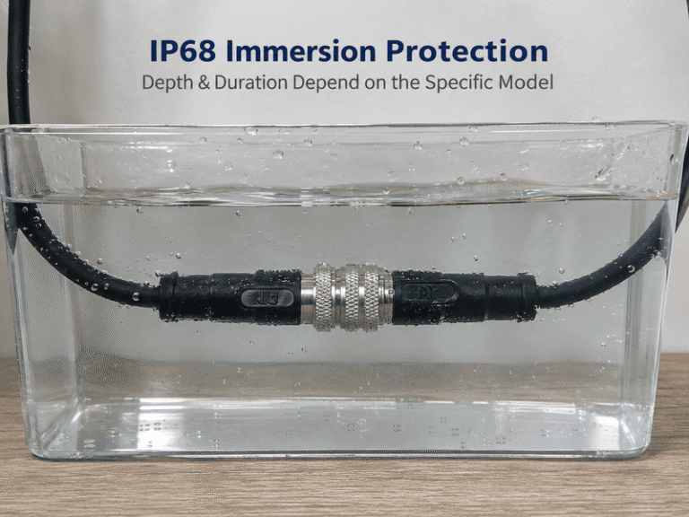
IP68 waterproof connectors are conditionally protected, not immune to water in every situation. When I discuss connector selection…

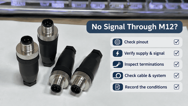
M12 problems can show up as a connector that will not mate, a device with no signal, intermittent dropouts, water ingress, or power loss under load. These symptoms are frustrating, especially when a machine is already running. I approach them by checking the complete connection path before deciding that the connector itself has failed.
Common M12 problems include mating difficulty, loss of signal, intermittent connections, water ingress, and power or temperature issues. Each symptom can have several causes in the connector, cable, termination, mating interface, or wider system. I start with a visual inspection, then check the connection and operating conditions against the product documentation before deciding whether to repair or replace anything.
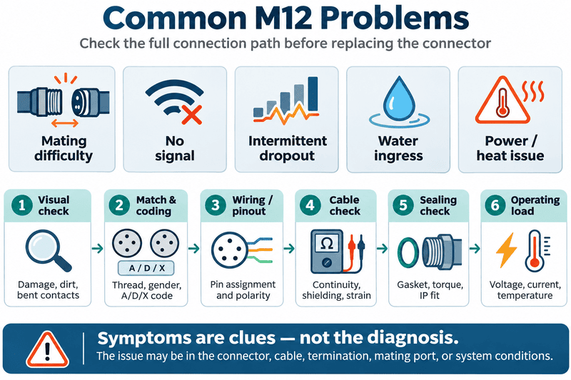
In my work with M12 selection, wiring, and customization discussions, I have found that symptoms are useful clues, but they are not diagnoses. A repeatable check sequence helps an OEM, integrator, or maintenance team narrow down the cause without overlooking the cable, device, or installation. Below, I organize the checks by symptom and separate general connection checks from Ethernet-specific ones.
A connector that will not mate may have the wrong coding, a misaligned key, contamination, or physical damage. I first compare the connector’s coding, pin arrangement, and orientation with the mating component. I avoid forcing the connection, because extra force can damage contacts or the coupling mechanism.1
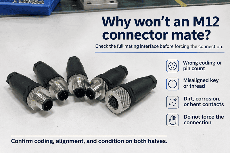
M12 connectors come in different codings and configurations.2 Two connectors can look similar but still be incompatible. A difference in coding, pin count, key position, or gender can prevent proper mating. The connector may also be the correct type but be presented at an angle, or it may have dirt, a damaged thread, or a bent contact.
I check both sides of the connection. A problem may be in the panel-mounted receptacle or device port rather than the cable connector. I also keep in mind that a connector can appear to engage without making a sound electrical connection if the contacts are damaged or the mating interface is not fully seated.
If the parts do not fit smoothly, I stop and confirm the part numbers and interface requirements. Forcing a mismatched or damaged connector can turn a compatibility question into a replacement issue. If there is visible damage, I do not treat repeated attempts to mate it as a useful diagnostic step. I set the affected connection aside for assessment.
No signal can result from an open circuit, incorrect pin assignment, poor termination, a damaged cable, or a fault in the connected device or system. I verify the wiring and pinout first, then check continuity with the connection safely isolated and use suitable test equipment to trace the signal path.
A “no signal” report can describe very different problems. The supply may be absent, the conductors may be assigned to the wrong pins, or a termination may be incomplete. A cable can also be damaged internally while its outer jacket looks normal. Beyond the connection itself, the sensor, actuator, PLC input, configuration, or other system component may be responsible.
I avoid assuming that a connector is faulty just because the device does not respond. A useful first step is to identify what signal should be present, where it should be measured, and under what operating condition. That helps separate a connection problem from a configuration or device problem.
For field-wireable connectors, the termination itself deserves close attention. The conductor may appear inserted while not being correctly secured, or the cable preparation may not match the connector’s assembly instructions. For molded cable assemblies, inspect the cable entry and connector body for damage, but do not assume that an intact exterior proves the conductors are undamaged.
I also keep the test boundaries clear: continuity can show whether an electrical path is open, but it does not confirm that a complete system is configured correctly or that a data link meets its performance requirements.3 When evidence points beyond the connector and cable, the device and control system need to be assessed too.
Intermittent dropouts during movement can come from conductor fatigue, a weak termination, strain at the cable exit, a tight bend, or a mating connection that is not secure. I note exactly when the fault occurs, then inspect the cable route and connection points before deciding that a loose connector is the cause.
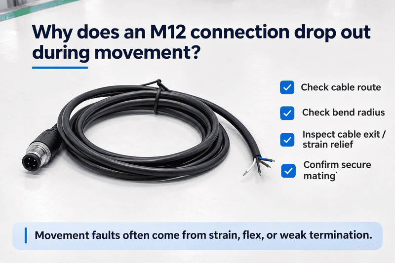
Movement-related faults can be difficult to reproduce on a stationary bench. The connection may work when the cable rests in one position but fail as the equipment moves. Possible causes include a damaged conductor inside the jacket, a termination that loses contact under flex, mechanical strain at the connector’s cable exit, or a bend that is tighter than the cable and installation allow.
A loose coupling is one possibility, but it is not the only one. The cable type and its suitability for the actual motion also matter. A cable jacket material, including PUR, does not by itself prove that the cable is suitable for a drag chain or repeated torsion.4 The required motion profile and the cable manufacturer’s application guidance need to be checked.
I find it helpful to record the cable position and machine state when the issue appears. That evidence can distinguish a movement-related cable problem from a fault that follows the device or control input. If the fault occurs only at a particular bend or travel position, the routing and flex conditions deserve attention. If the cable or connector shows cracks, exposed conductors, or other visible damage, stop using it and assess replacement rather than continuing to flex it during troubleshooting.
For suspected water ingress, I inspect the full sealing path: the mating face, cable entry, and panel mount. On field-wireable connectors, I confirm that the cable’s outer diameter matches the specified seal. I do not simply tighten the connector further, because torque requirements can differ by connection location and product.
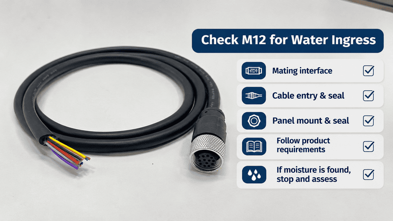
Water can enter at more than one point. The mating face may not be sealed correctly, the cable-entry seal may not match the cable, or the panel-mount interface may be compromised. A damaged seal, contaminated sealing surface, incorrectly assembled field-wireable connector, or installation outside the product instructions can also be relevant.
An ingress rating in a product document describes a defined product condition.5 It does not establish that every installed connection will provide the same protection in every environment. The installation method, mating parts, cable dimensions, panel preparation, and maintenance condition all matter.
I do not recommend applying more torque as a general fix. The appropriate torque can differ between a coupling nut, panel-mount hardware, and other parts of an assembly.6 Excessive tightening may damage components without correcting a mismatched seal or contaminated interface. I also avoid assuming that a connector’s rating alone settles the question. Buyers and installers should check the documentation for the exact product and configuration, then assess how the complete installed connection is being used.
Power loss or abnormal heating needs a check of the complete supply path under operating conditions. I measure voltage at the device while it is operating, and review inrush current, wire gauge and length, termination condition, and temperature. A power-supply reading without load or a connector rating alone cannot confirm circuit suitability.
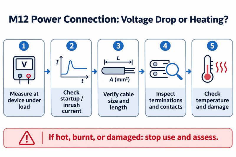
A voltage drop may come from a long or undersized cable, a poor termination, a supply limitation, or a load that draws more current during startup than expected.7 Heating may point to a connection or conductor issue, but the symptom needs qualified assessment. A connector’s current rating is one specification; it does not independently account for the full installed circuit, operating temperature, wire size, cable length, or duty cycle.
A normal output reading at the power supply when the circuit is unloaded does not show what reaches the device under operating conditions. I check the measurement point and load state so that the result reflects the actual installation. The same care applies to ratings: I compare the connector, cable, termination, and protection requirements as part of the whole circuit, rather than treating one rating as a complete answer.
If the connection is visibly damaged or abnormally hot, I do not continue running the equipment merely to collect more data. A qualified person should assess the circuit and decide whether the connector, cable, device, or another component needs replacement. Product-specific ratings and installation limits should be verified in the relevant documentation.
An Ethernet connection can show acceptable electrical continuity and still have data-performance problems. I check the correct Ethernet pinout, pair integrity, transmission performance, shield termination where applicable, and cable routing. These checks apply to Ethernet M12 links; they should not be assumed to apply to every M12 sensor, power, or control connection.
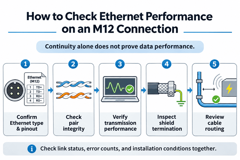
A basic continuity check can help identify an open conductor, but it does not confirm that an Ethernet link will perform correctly. The pair arrangement, cable construction, termination, shielding, and routing can all affect data performance. Interference from nearby equipment or an unsuitable cable path may also be worth investigating, depending on the installation.8
First, I confirm that the equipment and cable use compatible Ethernet interfaces and pin assignments. Then I use appropriate test methods for the required link and application. I do not use Ethernet guidance as a generic checklist for non-data M12 connections, because those products may have different functions and requirements.
I also look at what the network reports. Link status, error counts, or a fault that follows one cable can help narrow the investigation, but none of these observations alone proves a specific connector defect. The results should be considered alongside the physical inspection and the requirements of the actual Ethernet installation. If the connection is part of a critical machine network, a qualified network or controls professional can select the right test method and interpret the result.
I stop using an M12 connection when I find bent or pushed-back pins, corrosion, cracks, burn marks, or signs of water ingress. Those are reasons to isolate the affected connection according to site procedures and arrange an assessment. I do not troubleshoot by mating or unmating a live or loaded connection.
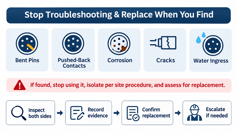
Visible damage can indicate that the connector, cable, mating port, or surrounding equipment needs further evaluation. A bent pin or pushed-back contact may prevent reliable connection. Corrosion and water marks may affect more than the visible surface. Cracks can compromise mechanical integrity, while burn marks or melted material can be evidence of a serious electrical or thermal problem.
Not every symptom means replacement is necessary. But when clear damage or ingress is present, repeated operation can make the condition harder to assess and may put connected equipment at risk. The appropriate next step depends on the product, application, and site procedures.
From a supplier-engineering perspective, I treat product selection and installation information as part of a reliable replacement decision. A replacement should match the required interface and application, not just the connector’s outside shape. Where the cause remains unclear, checking the cable assembly, mating equipment, and installation conditions can help prevent an unnecessary change or a repeat fault. I also recommend retaining the damaged part for assessment when the issue has procurement or quality implications.
No. A continuity test can identify some open-circuit conditions, but it does not confirm every aspect of an installed connection. Data links may need performance testing, and power circuits need assessment under operating conditions. The right test depends on the M12 application and its requirements.
Not automatically. The mating connection, cable entry, and panel mount have separate sealing considerations, and torque requirements can vary by location and product. Check the manufacturer’s instructions, inspect the seals, and confirm that the cable diameter matches the specified seal where applicable.
Not by material name alone. PUR describes a jacket material, but suitability for drag-chain or repeated-torsion use depends on the cable design and the actual motion conditions. Check the cable manufacturer’s application guidance and confirm that the cable is specified for the required movement.
No. I do not recommend troubleshooting by connecting or disconnecting a live or loaded connection.9 Follow the equipment’s isolation procedures and product instructions, and have a qualified person assess the circuit when needed.
Bent or pushed-back pins, corrosion, cracks, burn marks, or signs of water ingress warrant stopping use and assessing the connection for replacement. Inspect the mating equipment and cable as well, because damage may not be limited to one connector half.
Common M12 problems are best approached by symptom and a consistent first-check sequence. A connector that will not mate, a signal dropout, water ingress, or power loss can each have more than one cause. I check the connector, cable, termination, mating interface, and system conditions before drawing conclusions. Visible damage or signs of ingress call for stopping use and assessment. For application-specific selection or replacement, NITAI can support OEMs and integrators with M12 connector and cable-assembly options, engineering information, and customization discussions.
"(PDF) Non-Contact Wet Mateable Connector", https://www.academia.edu/11084292/Non_Contact_Wet_Mateable_Connector. Technical studies of electrical interconnects describe how misalignment and excessive mating force can damage contact and coupling features. Evidence role: mechanism; source type: research. Supports: A technical source should explain how misalignment or excessive mating force can deform contacts or damage connector coupling features.. Scope note: The degree and failure mode depend on connector design; this evidence does not specify an allowable force for every M12 product. ↩
"IEC 61076-2-101:2012", https://webstore.iec.ch/en/publication/4418. The applicable connector standard distinguishes M12 interfaces by coding and contact configuration; visual similarity alone does not establish interchangeability. Evidence role: definition; source type: institution. Supports: The relevant standard or technical institution should document that M12 connectors are available in distinct coding and contact configurations intended for different interfaces or applications.. Scope note: A general description of coding does not establish compatibility for a particular pair of products; their documentation must still be checked. ↩
"Network & Ethernet Cable Testing Guide", https://www.flukenetworks.com/blog/cabling-chronicles/network-and-cable-testing. Cable-testing guidance distinguishes continuity checks, which identify certain wiring faults, from performance tests that assess transmission parameters. Evidence role: general_support; source type: education. Supports: A standards-based or educational testing source should distinguish conductor continuity checks from qualification or certification of a data link.. Scope note: The exact tests required depend on the Ethernet category, link design, and applicable standards. ↩
"Cable Bending Radius & Flex-Life: A Practical Guide", https://www.l-com.com/resources/blog/proper-bending-radius-flex-life-continuous-motion-applications?srsltid=AYCX9vKNcsjtAyi5aKYmHwD1liDjF23QLQbOSrF8ZN6sDGL2JwBf5g9N. Cable-flexibility research relates service life under repeated motion to conductor, insulation, and cable construction as well as the imposed bend and torsion profile. Evidence role: mechanism; source type: research. Supports: A cable engineering source should relate flex life and torsional capability to construction and motion conditions, including bend radius and cycle profile.. Scope note: General findings cannot qualify a particular cable; application suitability requires the cable's tested specifications and the actual motion profile. ↩
"Ingress Protection (IP) ratings", https://www.iec.ch/ip-ratings. IEC 60529 defines enclosure protection classifications through specified tests for access, solid objects, and water ingress. Evidence role: definition; source type: institution. Supports: The applicable IP-code standard should establish that protection classifications correspond to specified tests and conditions.. Scope note: The classification alone does not establish the protection of an installed assembly with different mating parts, seals, or installation conditions. ↩
"Connector Torque Requirements", https://timesmicrowave.com/connector-torque-requirements/. Connector assembly guidance treats tightening torque as a component- and design-specific installation parameter. Evidence role: general_support; source type: research. Supports: A connector engineering source should support that assembly torque is specified for particular components and designs rather than being a universal value.. Scope note: General guidance cannot supply the correct value for a given product; the applicable product instructions remain necessary. ↩
"Inrush current", https://en.wikipedia.org/wiki/Inrush_current. Electrical circuit references describe load voltage as dependent on source capability and voltage drops across conductors and connections carrying current. Evidence role: mechanism; source type: education. Supports: Electrical engineering references should explain the relationship of conductor resistance, cable length, current demand, and source impedance to voltage at the load.. Scope note: The relative contribution of each factor depends on the circuit, load profile, and measurement conditions. ↩
"Managing Electromagnetic Interference in ...", https://www.slac.stanford.edu/econf/C140914/talks/tutub1_talk.pdf. Research on electromagnetic compatibility describes how nearby sources and cable installation geometry can couple interference into communication circuits. Evidence role: mechanism; source type: paper. Supports: Research or standards-based guidance should explain how electromagnetic coupling and installation proximity can affect communication cabling.. Scope note: The effect depends on the source, cable construction, shielding, separation, and installation; proximity alone does not prove a fault. ↩
"1910.333 - Selection and use of work practices.", http://www.osha.gov/laws-regs/regulations/standardnumber/1910/1910.333. Electrical safety guidance generally requires hazardous energy to be controlled before servicing electrical equipment and connections. Evidence role: general_support; source type: government. Supports: Government electrical-safety guidance should support isolating equipment before servicing or manipulating electrical connections where required by the applicable procedure.. Scope note: Whether a connection is designed for energized mating depends on its rating and the applicable procedure; this general guidance does not determine the capability of a specific M12 product. ↩
IP68 waterproof connectors are conditionally protected, not immune to water in every situation. When I discuss connector selection…
M12 connectors are not universal, although compatible interfaces may mate across brands. When I handle a replacement inquiry,…
The standard for M12 connectors is a frequent question in the inquiries and orders I handle, and the…
NITAI manufactures terminal blocks, M8/M12 waterproof connectors and industrial distribution modules for global OEMs, distributors and automation customers.
Leave a Reply