Oct 16, 2026
What Is an M12 Male Connector 5-Pin B-Coded?
An M12 male connector 5-pin B-coded may look like a straightforward line item, but its name does not…

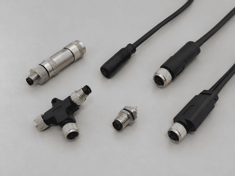
An M8 8 pin female connector can look like the right replacement on a purchasing list and still be wrong for the equipment. Eight contacts do not tell me what each circuit does, which way a pin drawing faces, or how the part mounts. I start with the device documentation, then check the proposed connector against it.
To select an M8 8 pin female connector, I confirm the exact device model and pin assignments, identify the viewing direction of each contact drawing, and compare coding, mating geometry, electrical ratings, and locking details. I then choose a cable-end connector or panel socket based on where it will be installed. The product name alone cannot establish compatibility.
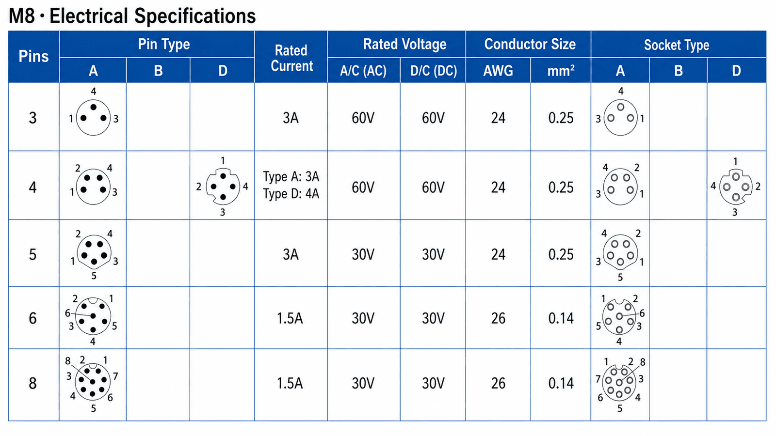
When I clarify an inquiry, I treat “M8, eight-pin, female” as a starting description—not an approved specification. The useful next step is to put the device schematic, mating-part drawing, and proposed assembly specification side by side. Each document answers a different question, and missing information becomes easier to spot.
A buyer may know the device has an eight-contact port but not have its wiring diagram. That gap matters: a connector can have enough contacts while carrying the wrong signals to the wrong places. Before I recommend a configuration, I ask what the equipment actually assigns to those contacts.
Eight contacts describe the interface’s contact count, not a universal wiring scheme.1 I need the exact equipment model, manufacturer pin assignment, connector coding, and intended cable or internal wiring. I also check voltage and current requirements against the proposed part’s documentation.2 If any assignment is unclear, I ask the equipment engineer to confirm it before purchasing proceeds.
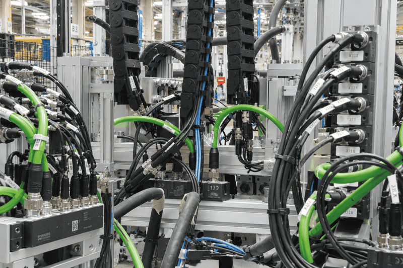
For an OEM replacement inquiry, I ask the buyer to send the full device model number and the relevant manual revision. A photo of the port helps identify its physical features, but it does not tell me which circuit belongs to each contact. I ask for the device manufacturer’s wiring diagram as a separate document.
A verified example shows why this matters. Balluff’s documentation for the BVS CA-GT1 identifies an M8 A-coded, eight-contact female multipurpose I/O interface. Its model-specific table includes digital I/O, RS232 receive and transmit, ground, and a power output. I use that example only to show how varied the functions can be within one device interface. I would not transfer Balluff’s assignments—or its listed cable colors—to another machine. I have not personally tested that product. (assets.balluff.com)
For a new design or replacement, I work through four questions:
I avoid treating an unused device contact as permission to omit a conductor, or an eight-core cable as proof that every circuit is correctly connected.3 If procurement needs a quote before engineering has finished the mapping, I mark the wiring as pending confirmation. That keeps a preliminary price discussion from becoming an accidental technical approval.
A drawing can appear clear until I ask where I am standing to view it. A mating-face view and a termination-side view look toward the same contacts from opposite directions. If I compare them as though they share one viewpoint, I risk approving an incorrect wiring map.
I identify the viewing direction before I compare contact numbers. I keep the connector’s mating-face drawing, the device schematic, and the assembly’s contact-to-conductor table separate. Then I reconcile their labels using the documentation for the exact parts. I do not assign numbers or wire colors from an unlabeled image.
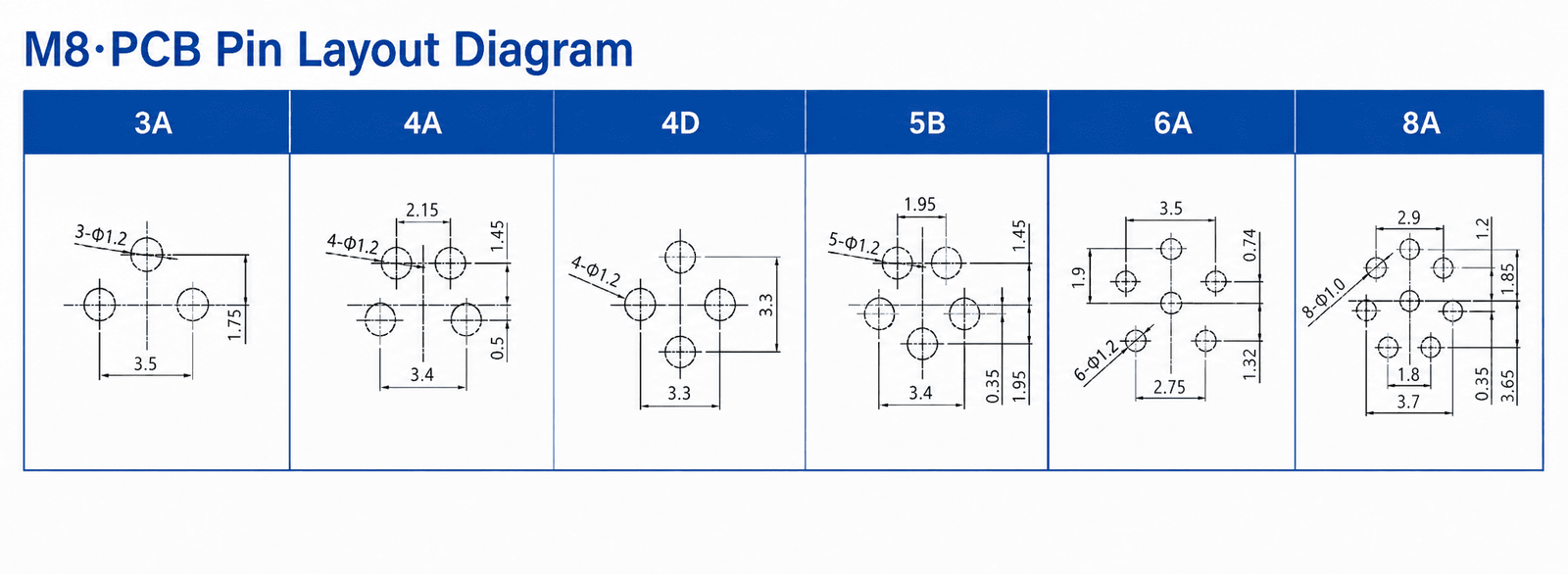
When I receive a pin diagram, I first look for words such as “view toward mating face,” “socket face,” “rear view,” or “termination side.” I also check whether the drawing depicts the female connector, its male counterpart, or the device port. If the label is missing, I request a labeled drawing rather than infer the direction from the page layout.
My review uses three distinct records:
| Record | What I use it to confirm |
|---|---|
| Device schematic or manual | The device manufacturer’s contact functions and electrical requirements |
| Connector contact drawing | Contact identification, gender, coding, and explicitly labeled viewing direction |
| Cable assembly wiring table | The documented connection from each contact to a conductor or opposite end |
I compare contact identity to contact identity first. Only after that do I compare the assembly’s wire identification. A cable color can be useful within one specified assembly, but I never use it as a substitute for the manufacturer’s contact-to-conductor table.4 Balluff’s BVS CA-GT1 documentation, for instance, explicitly labels its M8 illustration as a female top view and provides colors for a named cable; those details belong to that documented arrangement, not to every eight-contact M8 cable. (assets.balluff.com)
If two documents seem to disagree, I do not redraw the layout from memory. I ask whether they show opposite sides of the interface, whether one shows the mating counterpart, and whether both apply to the same revision. For a custom harness, I request an approved wiring table that names both connector ends and their viewing directions. An engineer can then check the mapping against the equipment before the assembly is released.
The purchasing description may identify size, contact count, and gender, but it leaves important physical questions open. I still need to know whether the connector keys to the device, whether its locking parts engage, and whether its body fits the space around the port.
I confirm mechanical compatibility against the actual mating counterpart.5 My check covers the specified coding, contact arrangement, mating-interface dimensions and thread, locking arrangement, and surrounding clearance. I check the exact product drawing rather than assume that every eight-contact female M8 part shares one construction. Electrical and mounting requirements remain separate checks.
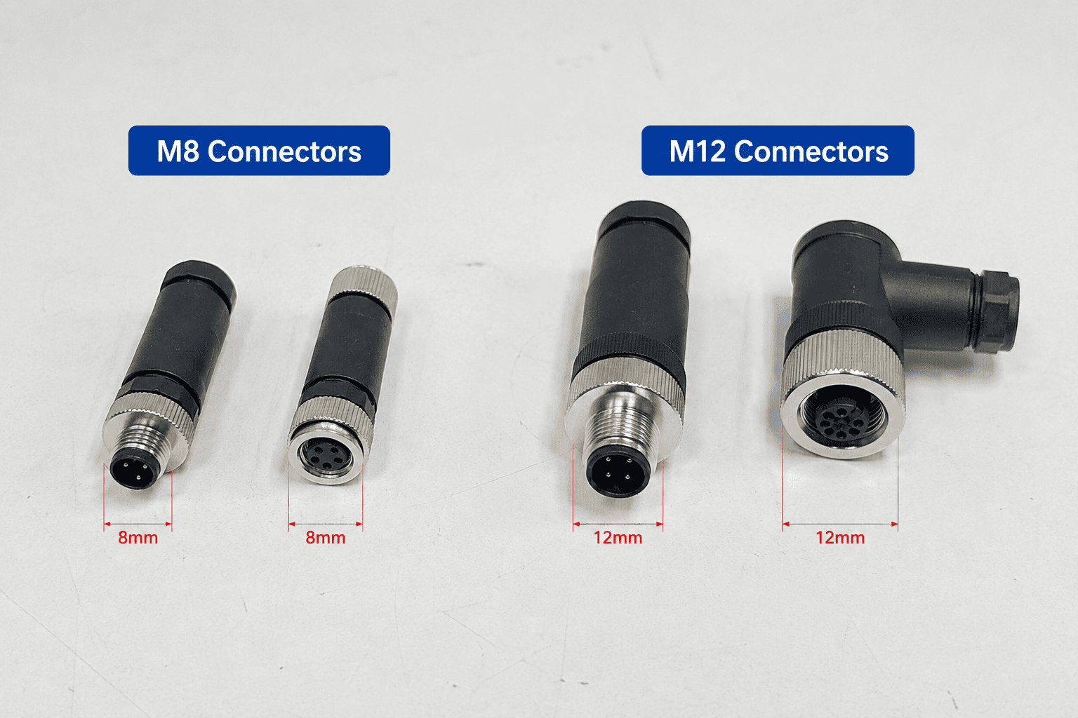
Phoenix Contact’s SACC-E-M8FS-8CON-M10/0,5, item 1424231, illustrates why I read a full specification. Its product page separately identifies an eight-position socket, A-coding, an M8 head interface, M10 front mounting, individual-wire termination, and a 0.5 m wire length. Those are attributes of that particular device-side product—not defaults for all female M8 connectors. I have not personally tested it. (phoenixcontact.com)
I give the mating interface and the panel mounting feature separate lines in my comparison. Where an exact drawing specifies an M8×1 mating connection, I check that specification against the counterpart; I do not infer it merely from the word “M8.” Likewise, a larger mounting-thread designation on a panel socket describes a different feature from its M8 mating face. That distinction is especially useful when an enclosure cutout is already fixed.
For an M8 8 pin female connector inquiry, my mechanical checklist includes:
I request a drawing for both halves when possible. If the buyer has only a photograph or a damaged sample, I can use it to narrow the inquiry, but I do not call it final proof of fit. I ask a qualified engineer to evaluate uncertain mating, environmental, or electrical requirements before approval.
A quote can go wrong even after the mating face is identified. “Female connector” may describe the contact side, while the buyer still needs either a cable end or a socket installed in equipment. I ask where the female interface will physically sit before selecting a purchasing category.
I choose the format by installation location and construction. A female cable-end part is specified for an assembly at the end of a cable; a female panel socket is specified for mounting in equipment.6 I then verify its mounting method, termination method, and whether a cable or individual wires are included. The category name alone does not settle every detail.7
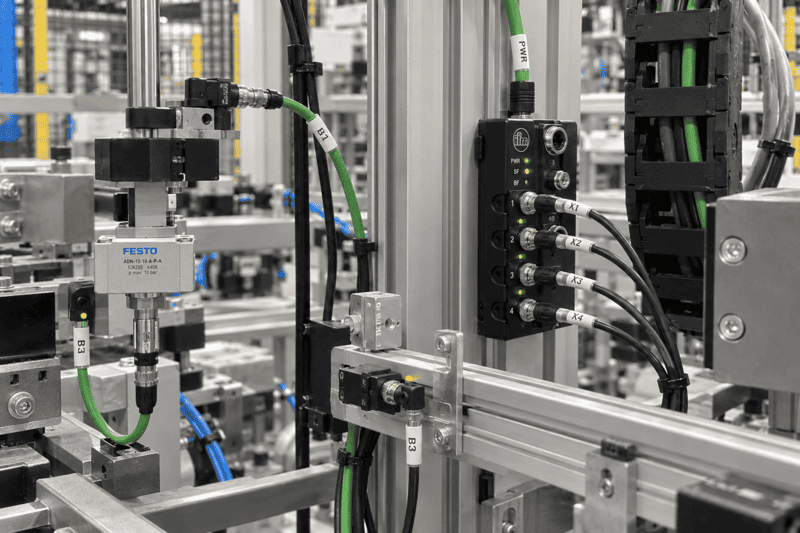
Here is the comparison I use when an RFQ says only “female M8, eight-pin”:
| Purchasing question | Cable-end option | Panel-socket option |
|---|---|---|
| Where will the female interface sit? | At the end of a specified cable or harness | In an equipment panel or enclosure |
| What installation detail matters? | Cable exit, route, length, and strain relief | Mounting direction, cutout, and available depth |
| What termination must be specified? | The assembly’s documented cable and wiring arrangement | The documented internal termination, such as wires, solder, or PCB connection |
| Is cable included? | I confirm its inclusion and specification | I check the exact product; a panel part can also have attached leads |
These are questions for the exact product, not guarantees about every item in either category. Phoenix Contact’s item 1424231, for example, is device-side and front-mounted, yet its page also specifies individual wires and a 0.5 m length. A panel designation therefore does not, by itself, mean “no attached wiring.” (phoenixcontact.com)
For a NITAI example, our published M8 Signal Type Back Mount Female Socket – Solder M12×1 page lists an eight-contact option among its pin-count choices. It describes a female M8 interface, rear panel mounting, solder termination, and an M12×1 mounting thread. I would ask the buyer to select and confirm the exact eight-contact coding and obtain the variant drawing before treating it as a match. I would not substitute that mounting-thread specification for an M8 mating-interface specification. (nitaix.com)
At NITAI, we can discuss connector selection, OEM/ODM requirements, custom cable assemblies, engineering drawings, and sample development. I still want the actual device and installation documents before proposing a final configuration. A sample can support a buyer’s fit review, while the equipment manufacturer or qualified engineer should confirm application-specific electrical and installation decisions. (nitaix.com)
No. I use the device manufacturer’s pin assignment and the exact connector or cable-assembly documentation. Eight contacts do not tell me which ones carry power, ground, control signals, or data. I would not copy a pinout from another device—even one with the same nominal connector description. (assets.balluff.com)
I can use a clear photo to begin checking contact gender, visible keying, and the surrounding installation space. I cannot establish the full wiring, ratings, or all mating dimensions from a photo alone. I also ask for the exact device model and labeled technical drawings before approving a replacement.
No. “Female” describes the contact interface, not its installation format. I ask whether the part belongs on a cable or in the equipment panel, then confirm mounting and termination details. I also check whether the quoted item includes a cable, attached leads, or neither. (phoenixcontact.com)
I recommend sending the device model and manual revision, its pin assignment, a labeled view of the mating port, the existing part number if available, and the required cable or panel installation details. I also ask for quantity and any applicable environmental or approval requirements so the proposed variant can be checked before quotation.
I select an M8 8 pin female connector by tracing the whole connection, not by matching a short product name. The device’s contact functions establish the wiring requirement; labeled drawings establish how I compare contacts; and the mating and installation drawings establish physical fit. If any of those records is missing, I keep the selection open rather than guess. Send NITAI your device model, wiring diagram, mating-part details, and installation drawing, and we can review the appropriate connector or custom assembly options with your engineering team.
"M8 vs M12 Connectors: Size, Pins, Coding, and Selection ...", https://amphenolltw.com/news-events/m8-vs-m12-connectors.html?srsltid=AU7gw4U2kfphwyy30S-pZcqp7D89ewUpOkigkSDGdFmny7LY2xjTKs4H. A connector designation specifies physical interface characteristics such as contact count and form factor, whereas the electrical function of each contact is defined by the relevant device or assembly wiring documentation. Evidence role: general_support; source type: research. Supports: The source should establish that contact count and physical connector designation do not, by themselves, define the electrical function assigned to each contact.. Scope note: A general connector reference supports the distinction between physical configuration and circuit assignment but does not verify the pinout of any particular device. ↩
"EEE-INST-002", https://snebulos.mit.edu/projects/reference/NASA-Generic/EEE-INST-002-DeratingPages.pdf. Connector suitability requires comparison of the application voltage and current with the rated limits of the specified connector under the relevant environmental and assembly conditions. Evidence role: mechanism; source type: paper. Supports: The source should describe how connector voltage and current ratings constrain application suitability and may depend on contact, temperature, spacing, and assembly conditions.. Scope note: Published ratings may be conditional on temperature, conductor size, mating state, and installation details; they do not by themselves prove system-level safety. ↩
"WAC 296-24-95707:", https://app.leg.wa.gov/wac/default.aspx?cite=296-24-95707. The number of cable conductors and the designation of an unused connector contact provide structural information but do not establish the required circuit mapping without the applicable schematic or harness wiring table. Evidence role: mechanism; source type: education. Supports: The source should explain that conductor count and unused-contact status must be determined from the circuit design and wiring documentation rather than inferred from physical count.. Scope note: The principle does not determine whether a conductor is needed in a particular device; that decision remains dependent on the equipment design. ↩
"Wiring Diagram Symbols Every Electrician Should Know", https://www.uti.edu/blog/electrical/electrical-wiring-diagram-symbols-guide. Conductor colors may identify broad wiring categories under applicable conventions, but the functional connection of a conductor to a connector contact remains dependent on the assembly wiring documentation. Evidence role: expert_consensus; source type: government. Supports: The source should distinguish conductor color identification from the functional assignment of a conductor within a particular equipment assembly.. Scope note: Color conventions differ across jurisdictions, industries, and product families; the source cannot validate the colors of a specific cable assembly. ↩
"M12 Connector Types: A, B, D, X, L, S, and T Coding Guide", https://amphenolltw.com/news-events/m12-connector-types-coding.html?srsltid=AU7gw4WY2auj6O_WYpAYxDTw4rBn2wLGn47e1GcT6x-MOohLzdk7kWf6. Mechanical interchangeability of circular connectors is governed by the specified interface geometry, keying or coding, dimensions, and locking arrangement, rather than by nominal size or contact count alone. Evidence role: general_support; source type: institution. Supports: The source should identify mating geometry, coding, dimensions, and locking features as factors governing whether two connector halves can mate.. Scope note: A standards-level source supports the evaluation criteria but does not establish compatibility for a particular manufacturer’s variant. ↩
"Gender of connectors and fasteners", https://en.wikipedia.org/wiki/Gender_of_connectors_and_fasteners. Connector gender describes the contact interface, whereas cable-mounted and panel-mounted classifications describe how the connector is incorporated into the equipment or cable assembly. Evidence role: definition; source type: encyclopedia. Supports: The source should define cable-mounted and panel-mounted connector configurations and distinguish installation method from contact gender.. Scope note: Terminology can vary among manufacturers, so product-specific construction and mounting details remain controlling. ↩
"TECHNICAL SPECIFICATIONS", https://fischerconnectors.com/app/uploads/2021/10/Fischer_Connectors_Technical_Specification_Volume_1_Catalogue.pdf. Connector family and category names are insufficient to establish a complete configuration because individual variants may differ in mounting method, termination, attached conductors, dimensions, and ratings. Evidence role: general_support; source type: research. Supports: The source should show that connector families contain variants differing in mounting, termination, cable, and dimensional attributes.. Scope note: The source supports the need for product-level verification but does not identify the attributes of a particular catalog item. ↩
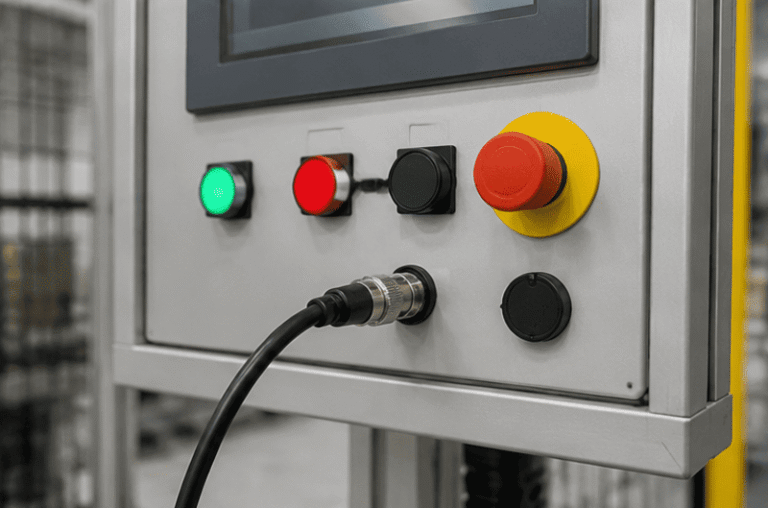
An M12 male connector 5-pin B-coded may look like a straightforward line item, but its name does not…
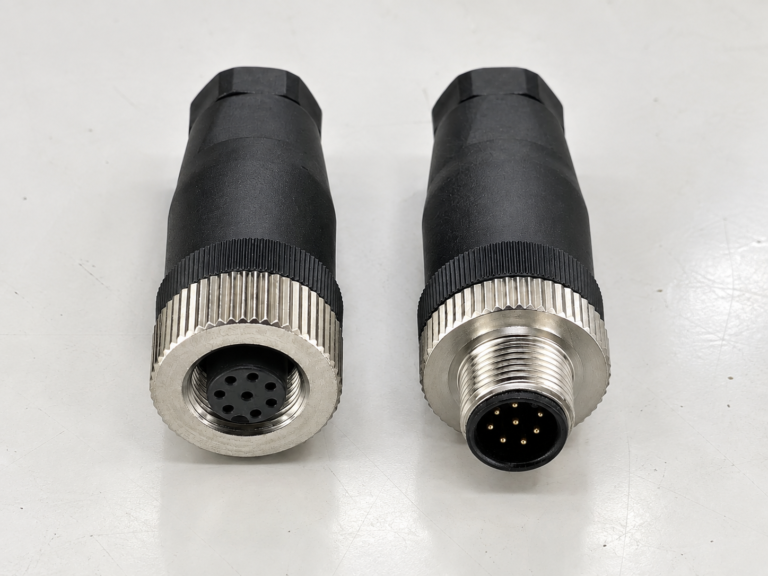
M12 connectors can carry different voltage ratings, so a buyer cannot choose one safely from the connector size…
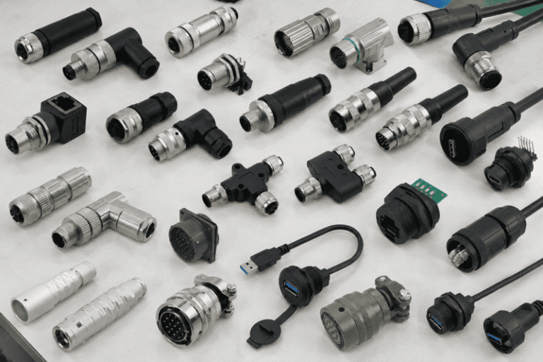
Connector types can look interchangeable in a catalog, but a familiar shape does not tell me whether two…
NITAI manufactures terminal blocks, M8/M12 waterproof connectors and industrial distribution modules for global OEMs, distributors and automation customers.
Leave a Reply