Oct 17, 2026
How Do I Choose the Right M8 8 Pin Female Connector for My Equipment?
An M8 8 pin female connector can look like the right replacement on a purchasing list and still…

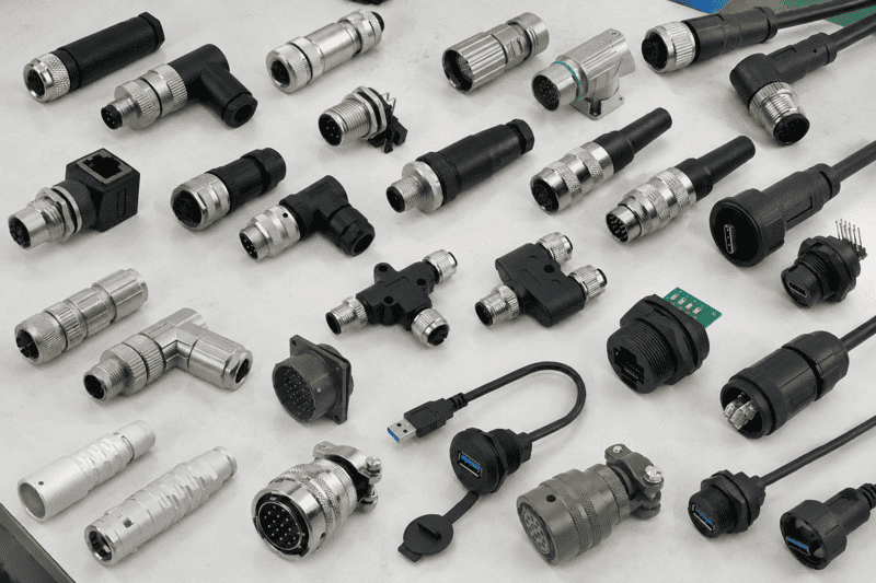
Connector types can look interchangeable in a catalog, but a familiar shape does not tell me whether two parts will mate or work in the same installation. A wrong choice can delay sampling or force a cable redesign. I find it more useful to identify the connection task first, then check the interface and installation requirements.
Common connector types include power, signal, data, board-to-board, and circular connectors. Each serves a different connection task. For industrial equipment, I narrow the choice by asking what the connector joins, where it will be installed, and which mating interface, contacts, electrical requirements, mounting method, and cable assembly the design needs.
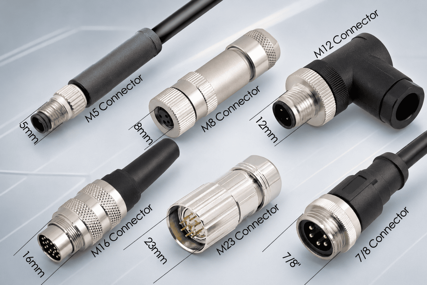
That broad list is a starting point, not a specification. A sensor connection on a machine, for example, needs different checks from a connection between two circuit boards. Below, I use those tasks to explain the main categories, then focus on the industrial circular connectors I most often discuss with equipment buyers.
When a buyer asks me for a “standard connector,” I first ask what needs to connect. The term covers several different tasks. If I assume the buyer means a cable connector when the design needs a PCB interface, even a promising sample may lead the team in the wrong direction.
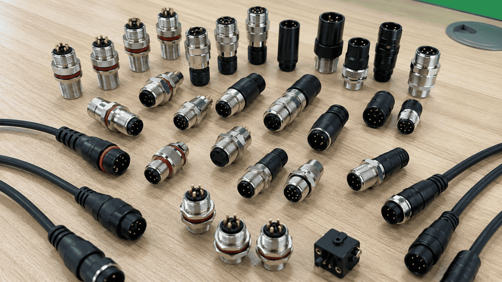
I group common connector types by what they join, not just by their shape. Power connectors carry energy to equipment or components. Signal connectors link devices such as sensors and controls. Data connectors support a specified communication interface.1 Board-to-board connectors join PCBs2, while circular connectors provide a round mating interface that can serve several industrial tasks.
| Connector category | What it commonly connects | First question I ask |
|---|---|---|
| Power | A supply or distribution point to a load | What voltage, current, and protection requirements apply? |
| Signal | A sensor, switch, or actuator to a controller | What signals and contact arrangement are required? |
| Data | Communication equipment or network nodes | Which protocol and specified interface does the system use? |
| Board-to-board | One PCB to another PCB | What spacing, orientation, and mating height does the assembly need? |
| Circular | A cable or device port to a round mating interface | Which exact series, coding, contact layout, and mounting style fit? |
These categories overlap. I may use a circular connector for signals, data, or power. Likewise, “data connector” describes a task; it does not identify a single physical part. That is why I move from the category to the device drawing and electrical requirements before suggesting a product.
I also keep connectors, terminal blocks, and finished cable assemblies distinct. A connector is a mating interface. A terminal block generally provides a wire-termination point in equipment or a panel. A finished cable assembly includes cable, connectors, terminations, and often application-specific length or routing requirements. A buyer may need all three in one control system, but I do not treat them as interchangeable items on a bill of materials.
I use the category to start the conversation. I use the mating drawing and application requirements to make the shortlist.
For a new design, this approach helps an engineering team avoid choosing by appearance alone. For replacement procurement, it helps a buyer establish whether an offered part can mate with the installed device rather than merely resemble the old connector in a photograph.
A catalog can show hundreds of possible parts before it tells me where the connection sits. That gap matters. A connector inside a protected control cabinet faces a different installation from one mounted on moving equipment. If I overlook mounting, cable movement, or the mating half, the electrical specification alone will not settle the choice.
I choose industrial connector types by defining the connection task and installed condition first. I then compare the specified mating interface, contact arrangement, electrical or data requirements, mounting method, cable construction, and environmental conditions. I ask the equipment team to confirm those details against product drawings and datasheets before it approves samples.
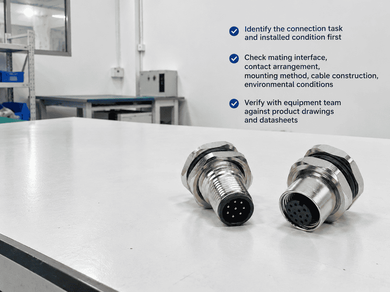
I use a short sequence when an inquiry begins with a photo or a broad request:
An anonymized inquiry illustrates the problem. A panel builder once approached me with a photo of a round connector and asked for “the same size.” I could not responsibly identify a replacement from the shell outline. I asked for the mating device model, a face-on view of its port, the existing part marking, and the cable requirements. Those details gave us a useful basis for comparing drawings. The photo alone had not established the coding or contact layout.
I treat a sample as a verification step, not proof that every installation condition is covered. I recommend that the buyer’s qualified engineering team check mating, pin assignment, fit in the enclosure, cable routing, and application-specific electrical performance before approving production. That work is especially important when a replacement part will mate with equipment supplied by another manufacturer.
Industrial circular connectors appear in many automation inquiries I handle, but the letter “M” and a size do not define an application. A buyer may see M8, M12, M16, or M23 in a catalog and assume that moving to a larger series solves a power or durability problem. That shortcut can hide incompatible contacts, coding, and mounting details.
I treat each M-series connector as a family of specified interfaces, not a universal rating. M8 and M12 often enter sensor and automation discussions, while M16 and M23 can arise in equipment interfaces that need different contact arrangements or package designs. I confirm each proposed part’s use through its manufacturer drawing, datasheet, mating information, and the device requirements.
M12 inquiries show why size alone is not enough. Coding describes a keying arrangement within the interface; it is one of several checks that affect mating. I commonly encounter the following distinctions in selection conversations:
| M12 coding | Common selection context | What I still verify |
|---|---|---|
| [A-coded | Sensor and actuator connections](https://en.wikipedia.org/wiki/IEC_metric_screw_sized_connectors)%%%FOOTNOTE_REF_3%%% | Contacts, pin assignment, electrical ratings, and mating part |
| B-coded | Certain industrial network or fieldbus interfaces | Required network interface and the specific product drawing |
| [D-coded | Certain industrial Ethernet interfaces](https://en.wikipedia.org/wiki/IEC_metric_screw_sized_connectors)%%%FOOTNOTE_REF_4%%% | Equipment port specification, contacts, and cable requirements |
| [X-coded | Certain higher-performance data interfaces](https://en.wikipedia.org/wiki/IEC_metric_screw_sized_connectors)%%%FOOTNOTE_REF_5%%% | Specified data application, shielding design, and complete assembly |
I do not use that table to promise that every part with a given code supports the same protocol, speed, or installation. The equipment specification and the individual connector documentation must support those claims. A matching M12 thread does not make differently coded parts compatible.6
M8 can be useful when equipment uses a compact circular port, including some sensor-related interfaces. I still check its specified coding or keying, contact count, ratings, and cable options. A small port does not tell me what the contacts carry.
M16 covers product designs with different contact configurations and termination choices. I ask for the intended mating half and drawing rather than assigning one typical electrical role to the whole series.
M23 may be considered for equipment interfaces that call for particular multi-contact arrangements. Its larger form does not, by itself, establish current capacity or suitability for a motor, signal, or mixed connection. The selected contact design and its published ratings matter.
For OEM and control-panel procurement, I find a side-by-side comparison more useful than a size ranking. I compare part number to part number: the interface drawing, contact layout, specified ratings, mounting dimensions, and compatible cable assembly. If a product or application is not documented, I leave it off the shortlist rather than fill the gap with a series-wide assumption.
A buyer can select the correct mating interface and still face trouble at installation. A poorly supported cable may pull on the termination.7 An enclosure seal may depend on the panel opening or mounting method. If I describe a connector only by its advertised IP rating, I leave out conditions that the finished equipment must meet.
I evaluate environmental protection as a property of the specified, installed connection under stated conditions. I check whether the rating applies when the parts are mated, how the cable and panel interfaces are sealed, and what the manufacturer’s test documentation covers. I also review cable strain, vibration, and shielding where the application requires them.

An IP designation is useful only when I know which assembly and conditions it describes. For example, a claimed IP67 rating is not a general promise of suitability for continuous immersion. I ask the supplier for the product’s stated configuration and supporting documentation, then have the equipment team assess the actual exposure and installation. A protective cap, an unmated connector, and a properly mated pair may have different documented conditions.
I pay similar attention to the mechanical path beyond the connector face:
These questions also shape supplier selection. I prefer a supplier that can provide consistent part identification, current 2D or 3D drawings where available, samples, and clear cable-assembly details. I ask buyers to verify any claimed certifications or standards compliance against the relevant documents and product revisions. For application-specific safety, electrical, or environmental decisions, I recommend review by a qualified professional rather than relying on a catalog description.
No. I check the specific product’s stated protection rating and the conditions under which it applies. Mating, cable sealing, panel installation, and test configuration can all matter. I do not assume that a round shape, an M-series name, or a protective cap makes a connector suitable for the equipment’s exposure.
Not necessarily. I compare coding, contact count, gender, keying, and the manufacturer’s mating information. I also check pin assignment and electrical or data requirements before recommending a sample. A shared M12 size identifies only part of the physical interface.
I recommend sending the existing part number, device model, mating-port drawing if available, clear photographs of the mating face, pin assignment, installation location, and cable requirements. I also ask for the needed quantity and any required documents. That information gives the supplier a basis for checking compatibility.
No. I use connector for the mating component and cable assembly for a finished cable with specified terminations. A cable assembly decision also involves cable type, length, conductor arrangement, shielding where required, and how each end connects. I specify both when sourcing a ready-to-install part.
Common connector types make more sense when I start with the task: power, signal, data, board-to-board, or a circular equipment interface. For industrial circular connectors, I then narrow the choice to the exact mating design, contacts, ratings, mounting, cable assembly, and installed conditions. I never use appearance, size, or an IP label as a substitute for those checks. If you are sourcing an interface for an OEM design or replacement, send NITAI your equipment requirements and available drawings. Our team can help you compare documented options and arrange samples for your engineering evaluation.
"Electrical Connectors: ~64k+ Types for Power, Signal, & Data", https://www.te.com/en/products/connectors.html. Educational descriptions distinguish connector functions such as power delivery, signal transmission, and data communication; these are functional categories rather than mutually exclusive physical designs. Evidence role: definition; source type: education. Supports: An educational reference should describe connectors by electrical function, including power delivery, signals, and communications.. Scope note: This classification does not establish the suitability of any individual connector. ↩
"Printed circuit board", https://en.wikipedia.org/wiki/Printed_circuit_board. Board-to-board connectors are used to make electrical connections between printed circuit boards; their dimensions and orientation depend on the assembly design. Evidence role: definition; source type: education. Supports: A technical educational source should define board-to-board connectors as interfaces between PCBs.. ↩
"IEC metric screw sized connectors", https://en.wikipedia.org/wiki/IEC_metric_screw_sized_connectors. Technical descriptions commonly associate A-coded M12 interfaces with sensor and actuator connections; the coding alone does not specify a part's pin assignment or electrical rating. Evidence role: general_support; source type: institution. Supports: A neutral technical or standards reference should associate A-coded M12 interfaces with sensor and actuator applications.. Scope note: The association is an application convention, not proof that every A-coded product suits a given sensor. ↩
"IEC metric screw sized connectors", https://en.wikipedia.org/wiki/IEC_metric_screw_sized_connectors. D-coded M12 interfaces are specified for certain industrial Ethernet uses; this identifies an interface type, not the performance of every connector or completed cable assembly. Evidence role: general_support; source type: institution. Supports: A standards or institutional reference should document the use of D-coded M12 interfaces in industrial Ethernet applications.. Scope note: The equipment specification remains necessary to establish protocol and assembly requirements. ↩
"IEC metric screw sized connectors", https://en.wikipedia.org/wiki/IEC_metric_screw_sized_connectors. Specifications for X-coded M12 interfaces address data-transmission applications with defined contact arrangements; the coding does not independently establish the speed or performance of an installed link. Evidence role: general_support; source type: institution. Supports: An interface specification should describe the data-transmission design associated with X-coded M12 connectors.. Scope note: Actual link performance also depends on the cable assembly and installation. ↩
"IEC metric screw sized connectors", https://en.wikipedia.org/wiki/IEC_metric_screw_sized_connectors. M12 interface specifications distinguish coding arrangements in addition to thread dimensions; a common thread designation does not, by itself, establish mating compatibility. Evidence role: mechanism; source type: institution. Supports: A connector standard should specify distinct coding or keying arrangements for M12 interfaces.. Scope note: Compatibility of specific products still requires their applicable drawings and specifications. ↩
"NASA-STD-8739.4A PDF", https://s3vi.ndc.nasa.gov/ssri-kb/static/resources/nasa-std-8739.4a.pdf. Electrical wiring guidance uses strain relief to limit the transfer of cable tension to terminations; the amount of support needed depends on the particular assembly and its loading. Evidence role: mechanism; source type: government. Supports: A government wiring or workmanship guide should explain the purpose of strain relief at electrical terminations.. Scope note: General wiring guidance does not establish whether a specific installation has adequate strain relief. ↩
An M8 8 pin female connector can look like the right replacement on a purchasing list and still…
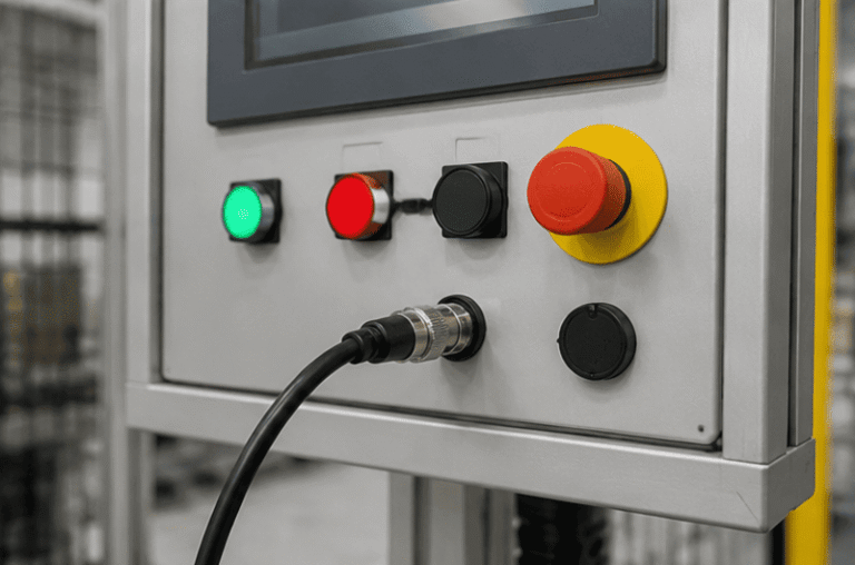
An M12 male connector 5-pin B-coded may look like a straightforward line item, but its name does not…
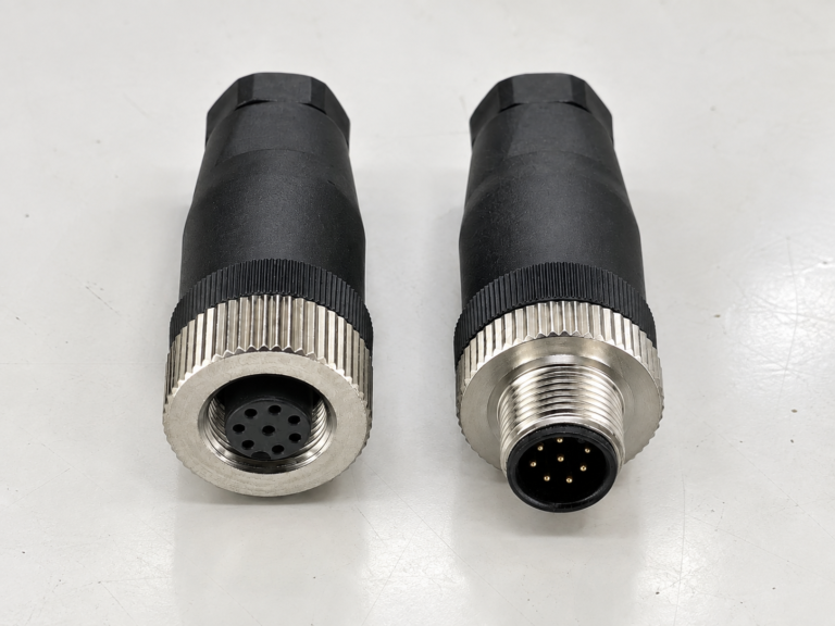
M12 connectors can carry different voltage ratings, so a buyer cannot choose one safely from the connector size…
NITAI manufactures terminal blocks, M8/M12 waterproof connectors and industrial distribution modules for global OEMs, distributors and automation customers.
Leave a Reply