Oct 17, 2026
How Do I Choose the Right M8 8 Pin Female Connector for My Equipment?
An M8 8 pin female connector can look like the right replacement on a purchasing list and still…

An M12 coding chart helps buyers distinguish connectors that look similar but serve different equipment functions. A wrong selection can stop a cable from mating or leave a device unable to operate, even when both ends are described as M12. I use the chart as a starting point, then verify the full connection against equipment and connector documentation.
An M12 coding chart compares the keyed mating arrangements used by different M12 connector types.1 It helps buyers identify a likely connector for a device function, such as sensor wiring, industrial communication, or power. The chart alone does not confirm compatibility: buyers must also check gender, contact count, pinout, ratings, and the complete part numbers of both mating ends.
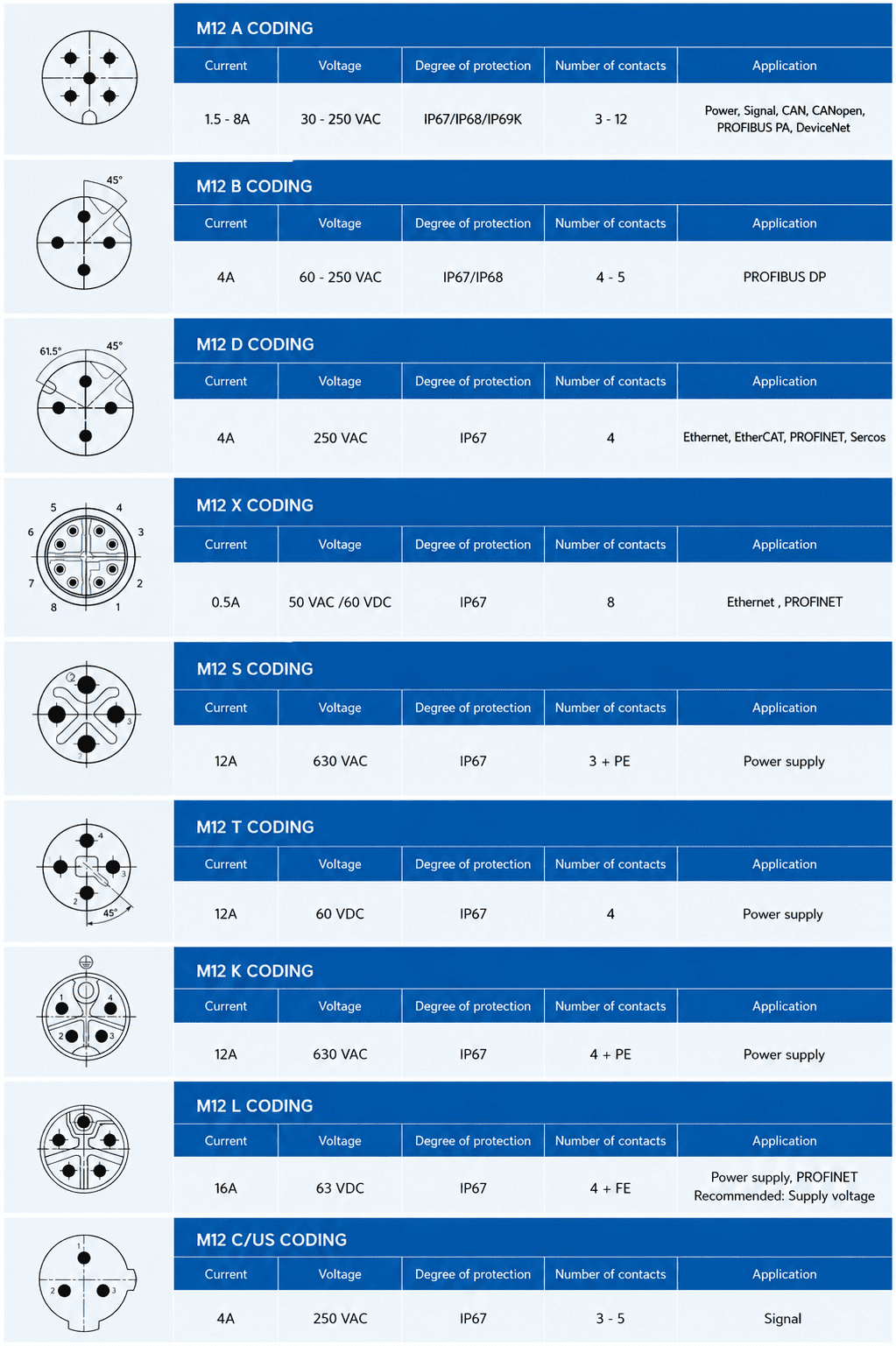
In my experience handling M12 selection and quotation questions, the letter on a drawing is often the first detail a customer sends. The more useful question is what the equipment port requires. Once I know that, I can work through the rest of the mating pair before anyone orders samples or schedules installation.
An M12 coding chart can look like a quick answer to a connector question. That is useful until two products share the same connector size but have different keyed interfaces. I treat the chart as a guide to physical coding and intended connection type, not as a complete wiring specification.
An M12 coding chart shows how named coding types distinguish mating interfaces and, often, the application categories commonly associated with them. Coding helps prevent an unsuitable connector from being used in a port intended for a different connection.2 It does not name a communication protocol3 or establish a pinout, electrical rating, or cross-brand match by itself.
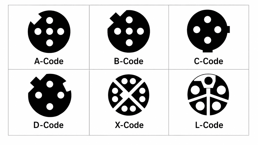
I commonly see buyers begin with familiar labels such as A-coded, D-coded, X-coded, or L-coded. Those labels matter because coding affects which mating interfaces are intended to fit together. They are not interchangeable shorthand for “an M12 connector,” however, and they do not tell me everything about the contacts or the cable assembly.
The examples below describe common application associations, not universal rules for every product bearing a coding label.
| Coding example | Common association | What I would still verify |
|---|---|---|
| [A-coded | Sensor and actuator connections](https://en.wikipedia.org/wiki/IEC_metric_screw_sized_connectors)%%%FOOTNOTE_REF_4%%% | Equipment port specification, contact count, pinout, and ratings |
| [D-coded | Certain industrial communication connections](https://webstore.iec.ch/en/publication/77773)%%%FOOTNOTE_REF_5%%% | Required interface, contact arrangement, and cable specification |
| [X-coded | Certain industrial Ethernet connections](https://en.wikipedia.org/wiki/IEC_metric_screw_sized_connectors)%%%FOOTNOTE_REF_6%%% | Equipment documentation, contact arrangement, and cable requirements |
| [L-coded | Certain DC power connections](https://en.wikipedia.org/wiki/IEC_metric_screw_sized_connectors)%%%FOOTNOTE_REF_7%%% | Voltage, current, contact assignment, and mating-part approval |
A chart is most helpful when it narrows a search. It cannot tell me whether a particular manufacturer’s cable assembly meets an equipment maker’s requirements. It also cannot resolve a vague request such as “an M12 Ethernet cable” without the equipment-side part details.
I make this distinction during purchasing discussions because a communication requirement and a connector coding requirement answer different questions. The equipment documentation may name a network or communication interface. The connector documentation describes the mating interface and the product’s construction. I check both, along with the specified cable and contact assignment, before recommending a part for evaluation.
I use a coding chart to identify candidates. I use the device and connector datasheets to confirm the connection.
A buyer can find an M12 cable with the right length and still receive the wrong item. If its coding does not match the equipment port, the planned connection may not mate as intended. That can delay commissioning, prompt a return, or leave a machine function unavailable while the correct assembly is sourced.
The equipment-side port and cable-side connector must have compatible coding because coding forms part of the intended mating interface. I confirm the port requirement from the equipment documentation and compare it with the proposed cable connector. I do not assume that two connectors will work together because they have the same nominal M12 size or a similar appearance8.
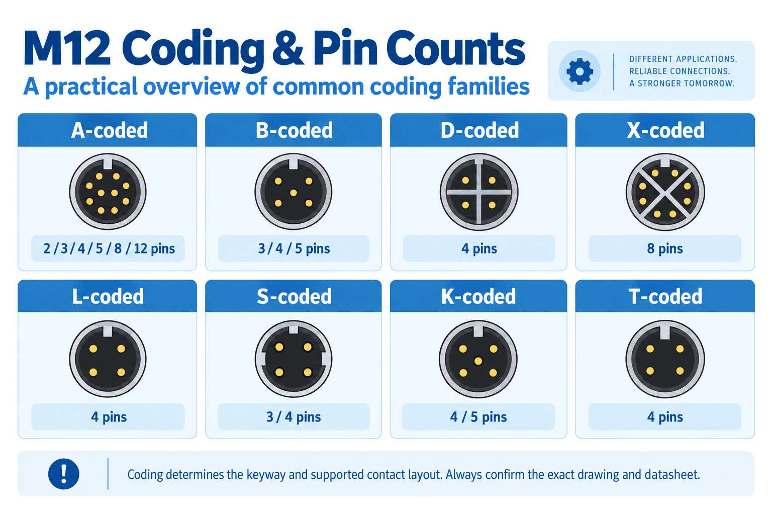
In customer pairing questions, I often receive a photo of a device port and a request for “the matching M12 cable.” A photo can help us ask better questions, but I would not treat it as final proof of coding. A keyed detail may be hard to see, and an outwardly similar connector may have a different contact arrangement or intended use.
Before quotation, I ask for the equipment model, port designation, and manufacturer documentation where available. I then compare those details with the proposed connector drawing and part number. That work matters because a mismatch may affect more than assembly time. A connection that cannot be completed can keep a sensor, actuator, network device, or power-fed component out of service.
I also avoid a second assumption: apparent physical fit does not prove electrical suitability9. If someone proposes an adapter or an alternative cable, I would still check the defined contact assignments, electrical limits, and equipment maker’s instructions. An application-specific decision belongs with the equipment documentation and a qualified electrical or controls professional.
I frame the check as two separate questions:
That comparison helps procurement teams catch an error before it reaches an installation crew. It also gives a supplier enough detail to confirm a mating option or identify an unresolved requirement.
A chart may point me toward the expected coding, yet leave several purchase-critical details unanswered. I have seen requests that specify the coding but omit the connector gender or the number of contacts. Those gaps can produce a quote for a plausible product that is not the product the equipment needs.
I check coding, gender, contact count, pinout, complete part number, and application together. I also review relevant electrical, environmental, cable, and mounting requirements in the applicable datasheets. No single chart entry establishes that an equipment port, mating connector, and cable assembly form a suitable connection.
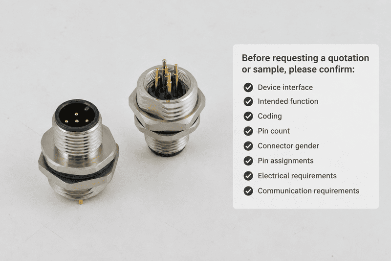
I use the following list when reviewing a new request for quotation. It is especially helpful when a buyer is sourcing a replacement across manufacturers or specifying a custom cable assembly.
The last item can cover several separate evaluations. For example, a purchasing team may need to confirm the assembly’s documented environmental protection, operating temperature, cable construction, and electrical ratings11. Those values depend on the exact products and installation conditions. I would ask a qualified engineer to assess them for the intended application.
A family name or catalog thumbnail rarely describes every orderable variation. Two assemblies in one product series may differ in length, cable type, termination, or connector configuration.12 For that reason, I ask customers to send the full equipment and proposed connector part numbers, not just “M12” and a coding letter.
The same approach applies to certification claims. If a project requires particular approvals or compliance evidence, I ask for the documents relevant to the exact proposed product and have the buyer verify that they meet the project’s requirements. A chart should not stand in for a datasheet, drawing, or approval document.
A chart is easy to consult after a buyer already has a part number. It is more valuable earlier, when the purchasing team needs to turn an equipment requirement into a clear inquiry. I use a short sequence so the chart guides selection without becoming the sole basis for it.
First, identify the device port and its function. Next, confirm the required M12 coding in the equipment documentation. Then compare the proposed mating connector’s complete datasheet, including gender, contacts, pinout, and ratings. Finally, resolve any gaps with the equipment maker or supplier before placing a production order.
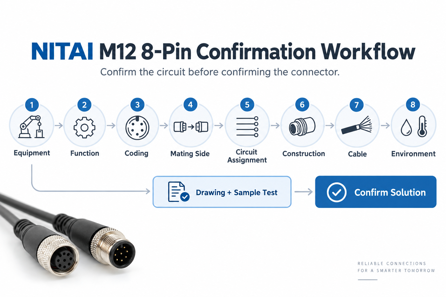
I would begin with the equipment manual or port drawing, not a general product search. The device maker’s information is the reference for what the port is intended to accept. If the manual provides only a broad description, I would request clarification before choosing a cable on appearance alone.
Once I have a documented requirement, I use the coding chart to narrow the connector category. I then compare the exact proposed product documentation. At this point, the chart has done its job: it has helped me find candidates, while the datasheets determine whether a candidate merits further evaluation.
A useful RFQ can be concise. I would include:
For a new equipment pairing, I recommend a sample review before a bulk order when the project schedule allows it. The buyer can compare the supplied part and documentation with the approved specification, while qualified personnel evaluate it in the intended system. That step is particularly important for custom assemblies or substitutions.
At NITAI, we support inquiries involving M12 connectors and custom industrial cable assemblies. Our team can use a customer’s equipment requirements to review available configurations and provide relevant product drawings or samples for evaluation. I still expect the buyer and their qualified technical team to confirm that the final selection meets the equipment maker’s requirements and the application’s conditions.
No. I treat M12 as the connector size designation, not a complete mating specification. I also check coding, gender, contact count, and the exact product drawings. If the connection carries power or signals, I verify the pinout and documented ratings before considering the pair suitable.
A clear photo may help me narrow the possibilities, but I would not rely on it alone for an order. I ask for the device model, port designation, and manufacturer documentation. Those sources are more dependable for confirming the required coding and the rest of the connection specification.
No. Coding describes a keyed connector interface; it is not a protocol name. I check the equipment documentation for its communication requirements, then check the connector and cable documentation for the specified mating arrangement and other requirements.
I ask for the equipment model and port details, the relevant manual or drawing, and any existing cable’s complete part number. I also ask for the desired length, termination, and installation conditions. That information lets me compare a proposed assembly against the actual requirement instead of guessing from a coding letter.
An M12 coding chart is a practical first step, but it is not a complete compatibility test. I use it to identify a likely keyed interface, then confirm the equipment-side requirement and check the proposed connector’s gender, contacts, pinout, part number, and documented ratings. That sequence helps buyers avoid unusable parts, installation delays, and preventable returns. For an M12 connector or custom cable inquiry, send NITAI the equipment port documentation and your required assembly details so our team can help you evaluate a suitable option.
"IEC metric screw sized connectors", https://en.wikipedia.org/wiki/IEC_metric_screw_sized_connectors. IEC 61076 specifications describe coding as a feature of M12 mating interfaces; a coding designation does not, by itself, identify a complete cable assembly. Evidence role: definition; source type: institution. Supports: A connector standard defines distinct coding and mating arrangements for M12 connectors.. Scope note: The standard defines interfaces rather than confirming the specifications of any product discussed here. ↩
"IEC metric screw sized connectors", https://en.wikipedia.org/wiki/IEC_metric_screw_sized_connectors. Mechanical keying restricts mating between differently configured connector interfaces, reducing the opportunity for an incorrect physical connection; it does not establish electrical compatibility between connectors that do mate. Evidence role: mechanism; source type: education. Supports: Mechanical keying constrains which connector interfaces can mate.. Scope note: This explains the mechanism of keying, not the failure rate or risk reduction in a particular installation. ↩
"Ethernet over twisted pair", https://en.wikipedia.org/wiki/Ethernet_over_twisted_pair. Connector-interface specifications and communication standards address different requirements: an M12 coding designation identifies a mating arrangement, not a communication protocol. A given device’s supported protocol must be determined separately. Evidence role: definition; source type: institution. Supports: Connector coding specifies a mating interface, while communication standards specify communication requirements.. Scope note: The distinction does not identify which protocols any particular M12-equipped device supports. ↩
"IEC metric screw sized connectors", https://en.wikipedia.org/wiki/IEC_metric_screw_sized_connectors. M12 A-coded interfaces are used for sensor and actuator connections; this application association does not establish the contact assignment or ratings of a particular assembly. Evidence role: general_support; source type: institution. Supports: Technical specifications or institutional guidance associate A-coded M12 interfaces with sensor and actuator connections.. Scope note: Common usage is not an exclusive rule for every A-coded product. ↩
"IEC 61076-2-101:2024", https://webstore.iec.ch/en/publication/77773. Specifications for M12 D-coded connectors provide a defined interface used in industrial data connections; the coding alone does not establish a device’s communication protocol or cable suitability. Evidence role: general_support; source type: institution. Supports: A recognized connector specification associates D-coded M12 interfaces with industrial data connections.. Scope note: The source would support an application association, not a universal use or a specific product match. ↩
"IEC metric screw sized connectors", https://en.wikipedia.org/wiki/IEC_metric_screw_sized_connectors. IEC 61076-2-109 specifies an X-coded M12 connector interface used for data connections, including industrial Ethernet applications; compliance with an interface specification does not verify a complete cable assembly’s performance. Evidence role: general_support; source type: institution. Supports: The X-coded M12 interface is specified for data-connection applications that include industrial Ethernet.. Scope note: The standard does not establish that every X-coded assembly meets a particular network installation’s requirements. ↩
"IEC metric screw sized connectors", https://en.wikipedia.org/wiki/IEC_metric_screw_sized_connectors. IEC 61076-2-111 describes M12 power-connector interfaces, including L coding for DC power applications; the applicable voltage, current, and contact assignment still require product-specific verification. Evidence role: general_support; source type: institution. Supports: A power-connector specification identifies an L-coded M12 interface used for DC power.. Scope note: An application category is not evidence that a particular L-coded part is suitable for a given load. ↩
"IEC metric screw sized connectors", https://en.wikipedia.org/wiki/IEC_metric_screw_sized_connectors. M12 connector specifications distinguish keyed mating interfaces within the M12 format; a shared size designation therefore does not, on its own, demonstrate that two specified ends will mate. Evidence role: mechanism; source type: institution. Supports: M12 connector specifications distinguish interfaces by coding in addition to the nominal connector size.. Scope note: Determining whether two actual parts mate requires their drawings or approved mating-part information. ↩
"SIST EN 61984:2009 - Connectors Safety Requirements ...", https://standards.iteh.ai/catalog/standards/sist/2864757d-54f8-45a1-a6d5-80f04e4b16ba/sist-en-61984-2009?srsltid=AU7gw4Werr0LoWsoU_XdnstlZfjPXVBDxF2QWuidLJUMr2JKWtA2Ec2p. Connector selection must account for electrical ratings and circuit assignments as well as the mating interface; physical engagement alone does not verify that the intended circuits are connected safely. Evidence role: mechanism; source type: institution. Supports: Electrical suitability depends on characteristics beyond the physical mating interface, including ratings and contact assignments.. Scope note: General connector requirements cannot establish the suitability of a specific adapter or device connection. ↩
"IEC metric screw sized connectors - Wikipedia", https://en.wikipedia.org/wiki/IEC_metric_screw_sized_connectors. M12 connector specifications describe multiple contact configurations within a coding category; buyers must therefore verify the specified contact count rather than infer it from the coding letter. Evidence role: general_support; source type: institution. Supports: Connector specifications include more than one contact configuration under an M12 coding designation.. Scope note: Available configurations depend on the coding and the applicable specification. ↩
"Ingress Protection (IP) ratings", https://www.iec.ch/ip-ratings. IEC 60529 addresses degrees of protection, while connector specifications separately address characteristics such as electrical ratings; neither characteristic follows solely from an M12 coding designation. Evidence role: general_support; source type: institution. Supports: Protection and electrical ratings are defined and evaluated separately from connector coding.. Scope note: These standards provide assessment frameworks, not the ratings of the particular cable assembly being purchased. ↩
"What Part A covers", https://www.medicare.gov/providers-services/original-medicare/part-a. A product-family designation need not identify an assembly’s length, cable construction, or termination; those attributes must be checked against the complete orderable specification. Evidence role: general_support; source type: education. Supports: Technical purchasing guidance distinguishes a product-family designation from the specifications of an orderable assembly.. Scope note: Which attributes are encoded in a part number varies by manufacturer, so the source would support the verification practice rather than decode any specific part number. ↩
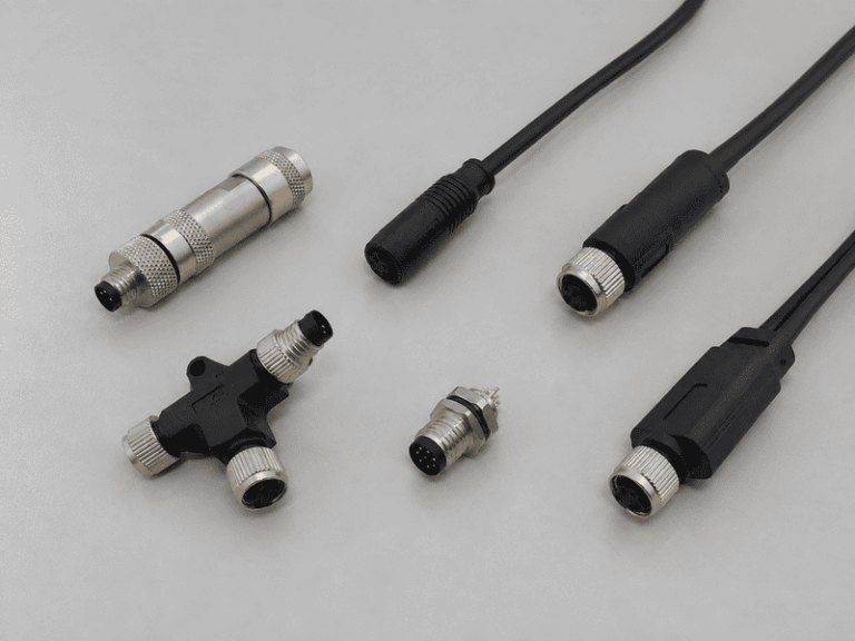
An M8 8 pin female connector can look like the right replacement on a purchasing list and still…
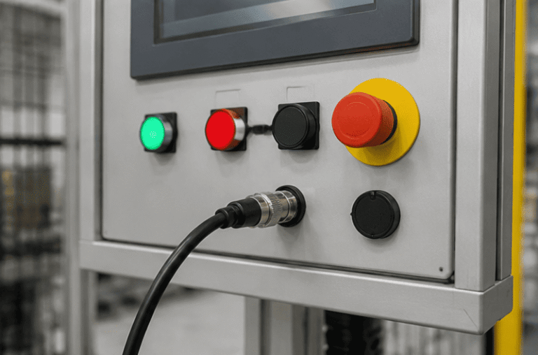
An M12 male connector 5-pin B-coded may look like a straightforward line item, but its name does not…
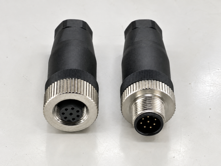
M12 connectors can carry different voltage ratings, so a buyer cannot choose one safely from the connector size…
NITAI manufactures terminal blocks, M8/M12 waterproof connectors and industrial distribution modules for global OEMs, distributors and automation customers.
Leave a Reply