Aug 20, 2026
PLC Interface Modules Explained: Types, Wiring, Functions and How to Choose
A PLC interface module is typically installed between a PLC I/O card and field wiring to make connections…

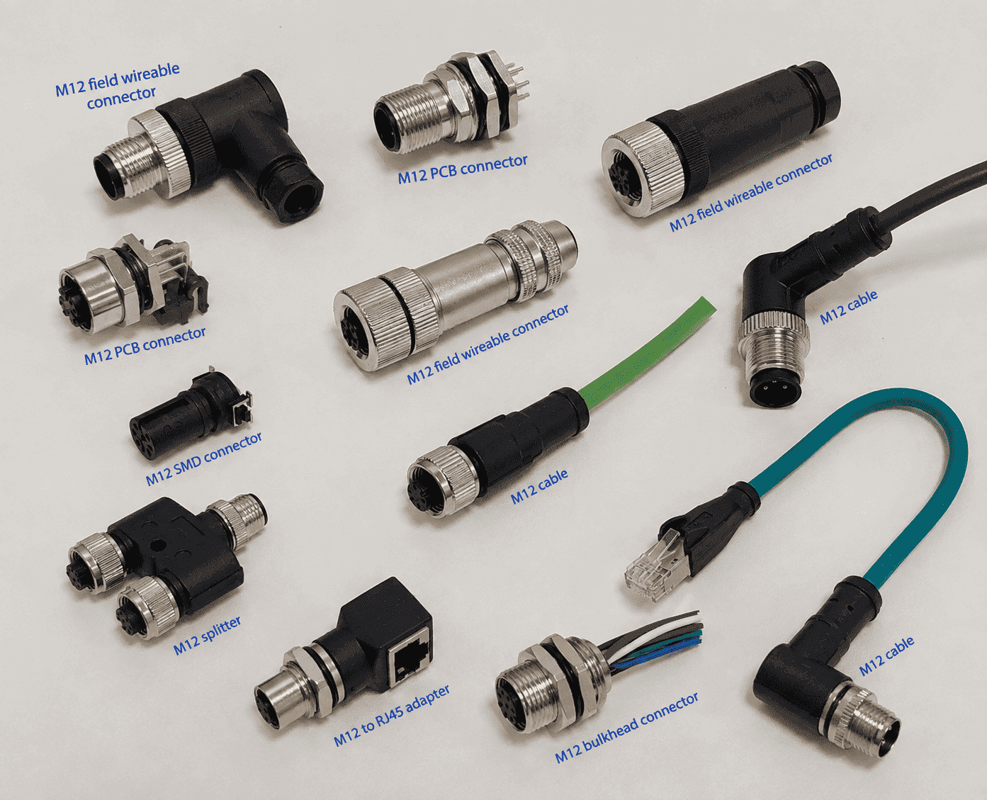
M12 connectors are easy to recognize as a family but surprisingly easy to misidentify as a specific part. Two products can have almost identical black molded bodies while using different contact patterns, coding keys, rear threads, or mounting dimensions.
An M12 connector is normally a compact circular industrial connector with an M12x1 screw-locking interface, a round mating face, pins or sockets, a coding keyway, and a sealing element. "M12" refers to the nominal locking-thread size - not the outside diameter or total length of the complete housing.
The front mating face is usually more informative than the side profile.
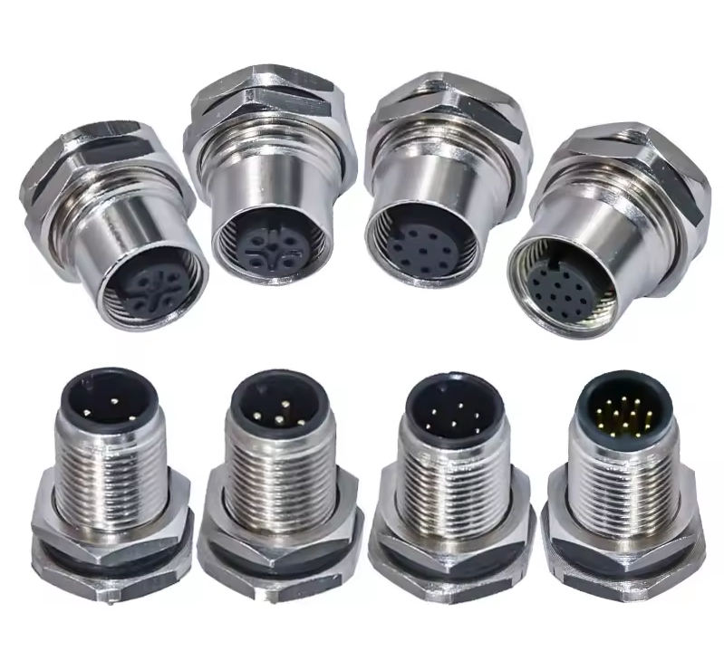
Look for a circular mating face, an M12x1 coupling thread or nut, numbered pins or sockets, a coding key, and a gasket or O-ring.
IEC describes this family as circular connectors with M12 screw locking used in industrial process measurement and control.1 The "M12" designation comes from the screw-locking thread dimension; it should not be read as "the whole plug is exactly 12 mm wide."2
A typical product includes:
| Visible feature | What it tells you | What it does not prove |
|---|---|---|
| Circular insert | It belongs to a circular connector family | Exact coding or pin assignment |
| M12x1 thread/nut | It may be an M12 interface | Housing length or rear thread |
| Pins or sockets | Male or female contact side | Cable-end gender from shell alone |
| Keyway / coding feature | Intended mating family | Electrical function without a datasheet |
| O-ring or face seal | Designed as part of a sealed interface | IP rating when unmated or poorly assembled |
| Metal shell | May support shielding and ruggedness | Correct 360-degree shield termination |
The coupling nut may be metal or plastic. The body may be molded TPU/PUR/PVC-compatible material, engineering plastic, die-cast metal, or machined metal, depending on the product design.
A male M12 connector has contact pins; a female M12 connector has contact sockets. The locking hardware alone does not determine electrical gender.
This matters because a female insert can be housed inside an externally threaded shell, while a male insert may sit behind a rotating coupling nut. Customers sometimes identify gender by looking only at the outer thread and end up ordering the opposite contact type.
Use the contact face:
Also state whether you are describing the cable end or device receptacle. Connector catalogs distinguish free cable connectors, fixed panel receptacles, and PCB-mounted versions.3
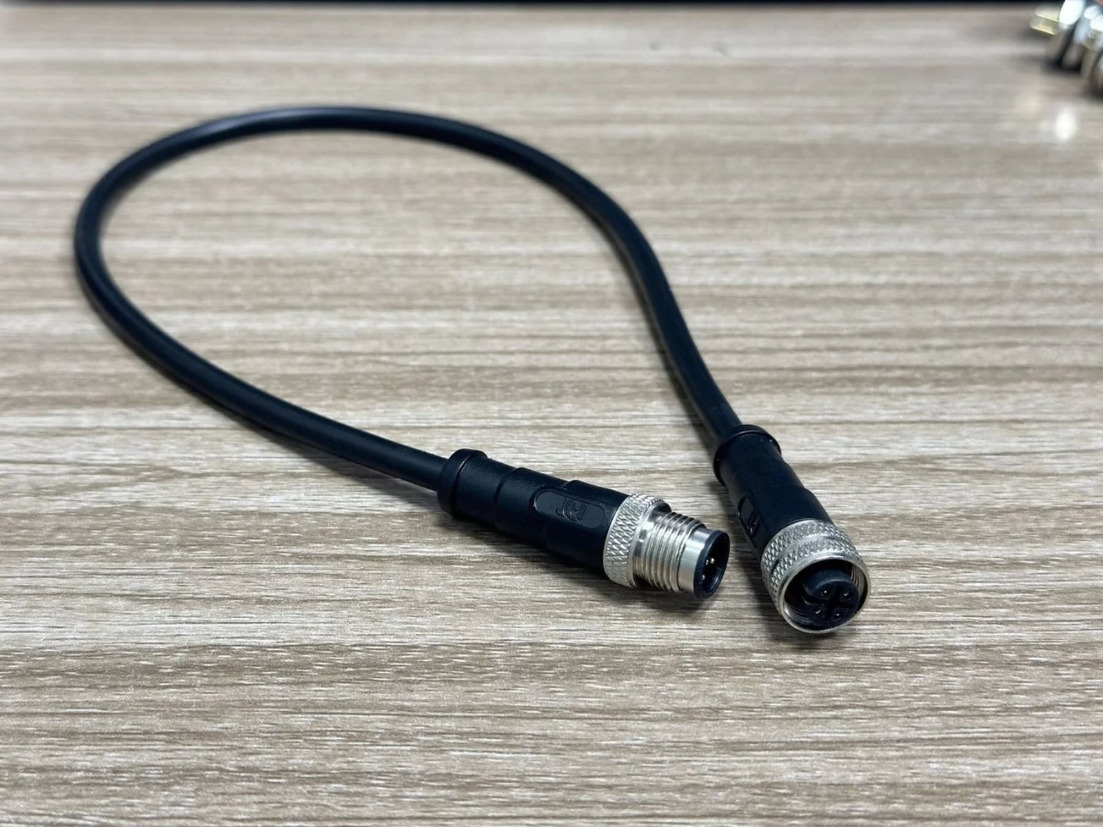
The mating face reveals the contact count, gender, and coding key - the three details that most often determine whether two M12 parts can mate.
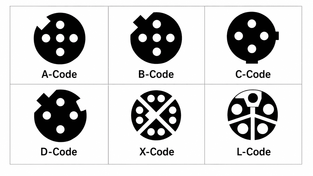
M12 coding uses form-fitting key positions to reduce mismating between interfaces intended for different purposes.4 A-, B-, D-, and X-coded products can all be described as M12 connectors, yet they do not share the same mating face.
This is why a side photo is often insufficient. From the inquiries we receive, a customer may send one image of a molded black connector and ask us to identify it. Several models can look nearly identical from that angle.
We normally request:
The front face identifies the interface; the remaining images and measurements identify the construction.
| Coding | Common visual clue | Typical use |
|---|---|---|
| A-coded | Single A-position keyway; many pin-count variants | Sensors, actuators, signals |
| B-coded | Different key orientation from A | Fieldbus applications |
| D-coded | D-position key; normally 4 contacts | 100 Mbps industrial Ethernet |
| X-coded | X-shaped internal divider; 8 contacts | High-speed industrial Ethernet |
| S/T/K/L | Power-oriented keyed forms | AC or DC power families |
Never determine coding from this simplified description alone. Compare the actual face with the dimensional drawing or an approved sample.
An M12 interface can appear as a straight plug, right-angle plug, molded cordset, field-wireable connector, panel receptacle, or PCB receptacle.
Commercial M12 ranges include cable connectors, flange connectors, molded cordsets, solder, crimp, screw, and dip-solder terminations.5 Panel products can also be designed for front or rear mounting, and multi-position versions are available for signal-dense equipment.6 Some M12 product families reach 17 contacts while retaining the M12 locking-interface concept.7
A straight connector extends along the cable axis. It is usually easier to route when there is enough depth behind the port. A right-angle connector turns the cable exit by approximately 90 degrees and can reduce required rear clearance, but its clocking direction must suit the equipment layout.
An overmolded connector is permanently molded to the cable. It offers controlled strain relief and repeatable sealing when correctly produced. The visible body shape depends on the mold design, so two brands may have different-looking overmolds while sharing a compatible mating interface.
These have a housing that opens for screw, spring, insulation-displacement, solder, or crimp termination. They are useful for field installation or repair, but correct cable diameter, gland compression, conductor preparation, and shield termination are essential.
Panel receptacles may mount from the front or rear and may include lead wires, solder cups, or direct PCB contacts. PCB versions need an exact footprint, mounting orientation, and board-side drawing - not a photo-based estimate.
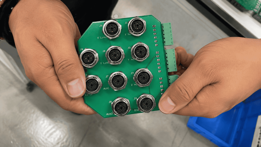
The standardized mating interface does not make every housing, overmold, cable exit, or rear mounting thread identical. Individual product drawings show that overall dimensions, cable exit, materials, and molded-body geometry remain product-specific.8
This is a practical detail we check frequently at NITAI. Different manufacturers may produce one compatible mating interface with:
For panel receptacles, rear threads such as M12x1, M15x1, M16x1.5, or PG-style structures may appear across product families. A side photo rarely reveals the pitch, usable thread length, panel cutout, or whether the receptacle is intended for front or rear mounting.
That is why we ask the customer to use a caliper. The standard mating circle may be clear, but the device integration can still fail if the housing is too high, the panel thread is wrong, or the PCB tail does not match the board.
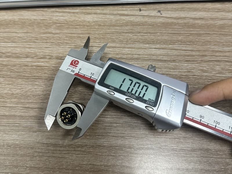
| Product type | Critical dimensions |
|---|---|
| Molded cable connector | body length, maximum diameter, cable OD, bend/strain-relief length |
| Right-angle connector | height above port, cable-exit direction, body width |
| Panel receptacle | panel cutout, mounting thread and pitch, usable thread length, front/rear mount |
| PCB receptacle | contact footprint, datum orientation, stand-off height, board thickness |
| Field-wireable connector | accepted cable OD, conductor size, gland range, assembly length |
Send a face photo, side photo, measurements, and application information; a single distant photo is rarely enough for reliable selection.
Our practical identification checklist is:
If the connector is still installed, photograph the device port as well as the cable end. If there is a label, capture it sharply. A readable manufacturer part number is often more valuable than five general photographs.
You can compare the general construction with our M12 connector products, then send us your photos and measurements for confirmation. We prefer to flag an uncertain detail before quotation rather than let a visually similar but incompatible connector reach your machine.
When no reliable drawing or part number exists, a physical sample is the safest route. Test:
No. Similar-looking circular connectors can use push-pull, bayonet, snap, or different screw threads. Measure the interface and inspect the keying.
No. It refers to the nominal M12 locking-thread interface. The coupling nut and molded body are normally larger.
Not reliably. The same contact count can exist in different coding families. Keyway position and the specified standard must also match.
No. Determine gender from pins versus sockets, not from the shell thread or coupling nut.
No. The mating interface can be M12 while the mounting or rear termination geometry varies. Confirm the exact dimensional drawing.
Housing, shielding, termination method, overmold, strain relief, and cable OD all affect overall dimensions while the mating interface can remain compatible.
A sharp, straight-on mating-face photo with the keyway at a known orientation, followed by a side view beside a ruler or caliper.
An M12 connector normally looks like a small circular industrial plug or receptacle with an M12x1 screw lock, contacts, a keyway, and a seal. But that appearance is only the beginning of identification.
Use the mating face to establish contact count, gender, and coding. Use side views, caliper measurements, equipment details, and the manufacturer drawing to determine the exact housing, rear thread, and mounting form. If a project is moving toward production, validate a real sample rather than approving it from a side photo.
[IEC 61076-2-101:2024](https://webstore.iec.ch/en/publication/77773) - Defines the M12 screw-locking circular connector family for industrial applications. ↩
[IEC 61076-2-101 preview](https://elstandard.se/documents/preview/303401) - Identifies M12 as the screw-locking thread dimension and explains coding. ↩
[TE Connectivity M8/M12 Connector System](https://www.te.com/en/products/connectors/circular-connectors/intersection/m8m12.html) - Shows cable, panel, and PCB-oriented product forms within the family. ↩
[binder Product Overview](https://www.binder-connector.com/en/products) - Explains that connector coding provides form-fitting alignment and reduces mismating. ↩
[binder M12 A-Coded Range](https://www.binder-connector.com/uk/products/automation-technology/m12-a) - Supports the range of cable, flange, molded, solder, crimp, and PCB termination forms. ↩
[Phoenix Contact M12 XL Panel Feedthroughs](https://www.phoenixcontact.com/en-us/us-lp-m12xl) - Shows front/rear mounting and multiple position counts in panel products. ↩
[Phoenix Contact 17-Position M12 Products](https://www.phoenixcontact.com/en-be/cat/m12-male-17-pos-2164) - Demonstrates that M12 appearance and pin density can vary substantially. ↩
[binder M12 Product Example](https://www.binder-connector.com/en/products/automation-technology/m12-a/77-3430-0000-20004-0500-m12-a-female-cable-connector-contacts-4-unshielded-moulded-on-cable-ip69k-ul-pvc-grey-4-x-034-mm2-5-m) - Provides an example of a molded M12 product drawing, dimensions, materials, and rating details. ↩
A PLC interface module is typically installed between a PLC I/O card and field wiring to make connections…
A four-pin M12 connector is not automatically a sensor connector. In industrial automation, a visually similar four-contact product…
A customer asks for a “standard M12 pinout.” It sounds like a simple request, but a pin diagram…
NITAI manufactures terminal blocks, M8/M12 waterproof connectors and industrial distribution modules for global OEMs, distributors and automation customers.
Leave a Reply