Oct 17, 2026
How Do I Choose the Right M8 8 Pin Female Connector for My Equipment?
An M8 8 pin female connector can look like the right replacement on a purchasing list and still…

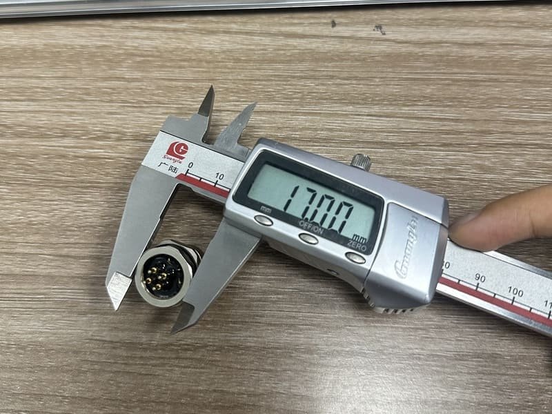
A customer asks for a “standard M12 pinout.” It sounds like a simple request, but a pin diagram can be dangerously incomplete if it does not identify the coding, number of contacts, connector gender, viewing direction, and equipment function.
M12 describes a connector interface family, not one universal circuit.
There is no single functional M12 connector pinout for every M12 product. The physical contact positions are standardized within a selected coding and contact count, but the electrical function assigned to each contact still depends on the application and the equipment manufacturer.
For example, a common A-coded 4-pin sensor cable uses Pin 1/brown, Pin 2/white, Pin 3/blue, and Pin 4/black. That color-to-pin convention does not prove that every connected device gives the same job to Pin 2 or Pin 4. The device wiring diagram remains the final authority.
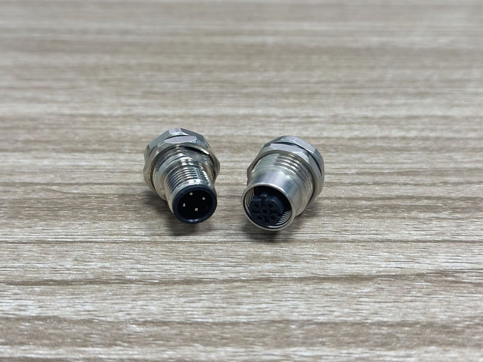
No. “M12” identifies the interface family; it does not specify one wiring diagram.
The IEC product standard covers M12 screw-locking connectors with multiple contact counts and configurations. It describes products from 2 to 17 ways and separates their mechanical and electrical requirements by application.1 The coding key then helps prevent connectors intended for different functions from being cross-mated.2
Before a pinout is useful, six questions must be answered:
This distinction matters: contact position and circuit function are not the same thing. A standard may fix where “Pin 1” is located on a particular interface. The machine builder determines whether that pin carries supply voltage, a signal, data, protective earth, or another function—unless an application standard also defines it.
For a widely used A-coded 4-pin sensor cable, the common wire-color sequence is Pin 1 brown, Pin 2 white, Pin 3 blue, and Pin 4 black.
IEC 60947-5-2-based sensor connection documents show this familiar color assignment,3 while the IO-Link design guideline uses Pins 1, 3, and 4 for a typical Class A port and treats Pin 2 as an optional additional signal.4
| Pin | Common conductor color | Common sensor / IO-Link use | Important limitation |
|---|---|---|---|
| 1 | Brown | L+ supply | Confirm device voltage and drawing |
| 2 | White | Optional or second signal | Function varies by device |
| 3 | Blue | L− / 0 V | Confirm polarity before energizing |
| 4 | Black | Switching signal or IO-Link C/Q | Not universal across all equipment |
This is a useful starting point, not permission to wire from memory. A pressure sensor, actuator, splitter, custom machine port, and proprietary device can assign functions differently.
An M12 5-pin A-coded connector adds another contact, but the extra pin does not automatically have one universal job. It may be used for an additional signal, functional earth, or a device-specific circuit. The equipment schematic must be checked.
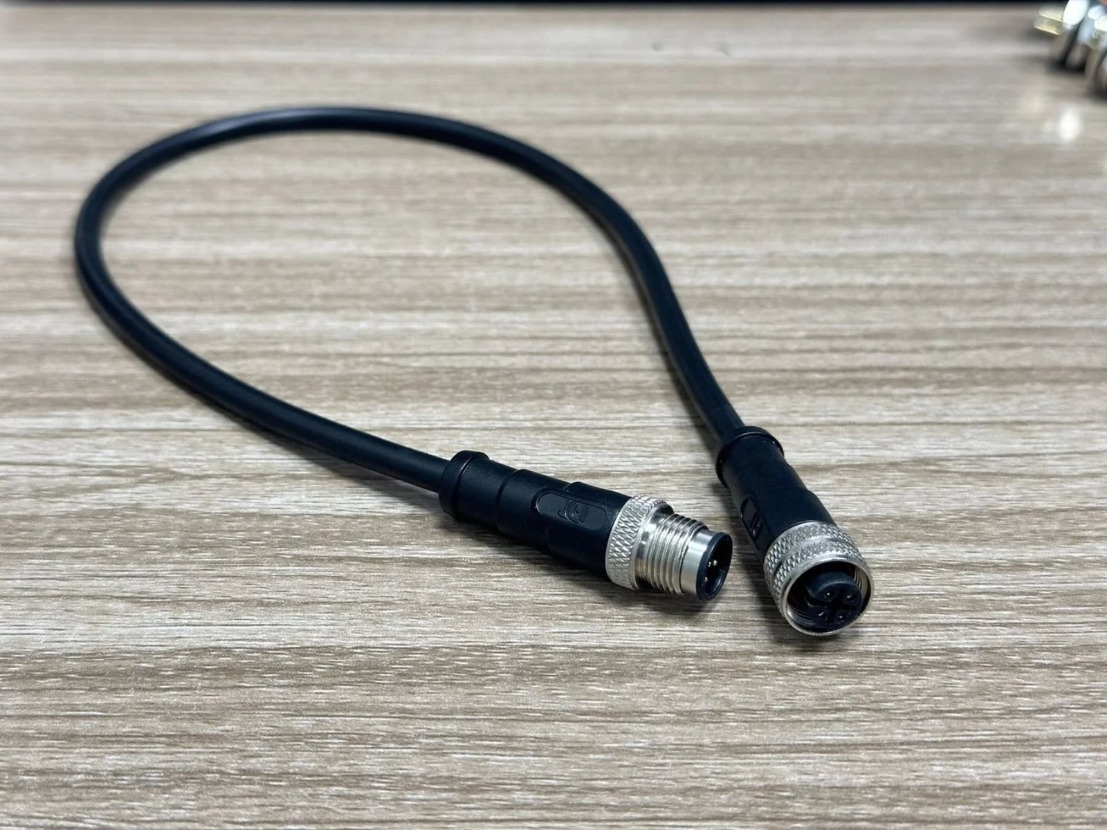
A male and female connector can appear mirrored when both drawings are shown from their own mating faces.
This is one of the most common causes of field-wiring errors. A technician sees a correct online diagram, but the drawing is from the mating side while the connector in hand is being viewed from the solder or wiring side. Pin numbers then appear reversed.
Reliable connector drawings normally state a viewing direction such as:
Manufacturer drawings of M12 receptacles often provide separate face views and pin assignments precisely because the viewpoint matters.5
At NITAI, when a customer sends us a hand-marked wiring image, we do not copy it directly into production. We first label:
Only then do we convert it into a production wiring table.
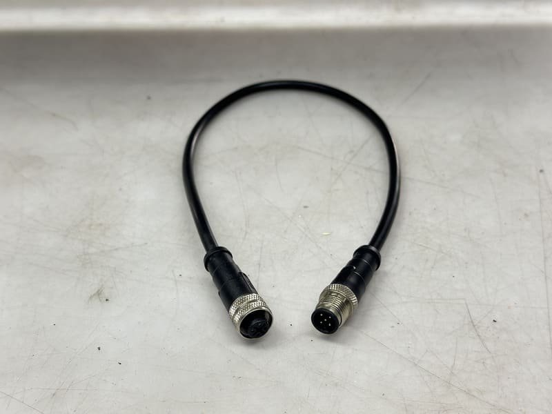
Instead of writing “left contact to red wire,” specify:
| End | Coding / gender | Pin number | Conductor | Opposite-end destination |
|---|---|---|---|---|
| End A | M12 A-coded male | 1 | Brown | End B Pin 1 |
| End A | M12 A-coded male | 2 | White | End B Pin 2 |
| End A | M12 A-coded male | 3 | Blue | End B Pin 3 |
| End A | M12 A-coded male | 4 | Black | End B Pin 4 |
That format removes the ambiguity created by screen orientation.
Once the coding, contact count, and interface are selected, the mating geometry and contact arrangement are not free-form.
This is the part that often causes confusion. We say there is no universal functional pinout, but that does not mean a standard connector face can be rearranged to any pattern.
The standard interface controls items such as:
A useful example came from a recent sample project—not an M12 order, but an M8 6-pin connector with the same practical lesson. The customer bought a standard sample and later found it would not fit the holes in their PCB. The bottom three PCB holes had been designed in a straight row, while the connector used the standard 6-pin contact pattern.
The customer asked whether we could move the contacts. For that standard interface, the answer was no: changing the mating or PCB contact arrangement would stop it from being the standard product they selected. The correct solution was to revise the PCB footprint to the specified connector drawing.
The lesson is simple: custom cable wiring is possible; arbitrary changes to a standardized mating pattern are not. Before releasing a PCB, always obtain the exact manufacturer drawing and verify the footprint, orientation, mounting face, and tolerances.
D-coded and X-coded connectors use application-specific Ethernet arrangements and must not be wired as though they were A-coded sensor connectors.
D-coded M12 Ethernet commonly uses four contacts and two data pairs for 100BASE-TX industrial networks. PROFINET guidance specifies the D-coded M12 interface for rugged 4-wire Ethernet connections and emphasizes correct shield termination.6
X-coded M12 uses eight contacts divided into four pairs. IEC 61076-2-109 addresses this M12 interface for data frequencies up to 500 MHz,7 and commercial systems use it for Category 6A and transmission up to 10 Gbps.8
| Coding | Common role | Typical contacts | Do not assume |
|---|---|---|---|
| A-coded | Sensors, actuators, general signals | 3, 4, 5 and others | Ethernet pair assignment |
| D-coded | 100 Mbps industrial Ethernet | 4 | A-coded sensor wiring |
| X-coded | High-speed industrial Ethernet | 8 | Any ordinary 8-core cable will deliver 10 Gbps |
The coding key prevents direct interconnection between unlike interfaces. If a customer asks us to make an adapter between different connector families, we also verify whether an electrical conversion—not merely a physical cable—is required.
Before we quote or build, we convert the customer’s request into a controlled connector-and-wiring specification.
From the inquiries we receive, “M12 4-pin cable, two meters” is one of the most common incomplete descriptions. Our follow-up is usually:
For standard sensor-cable requirements, our M12 connector range provides a starting point. A customer who already knows they need a four-contact assembly can also review our M12 4-pin connector options, but the pin assignment still has to be confirmed before production.
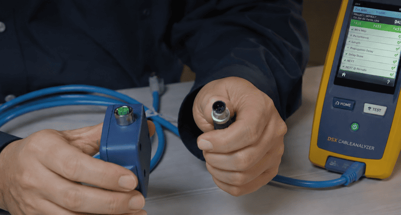
We normally recommend checking a sample against the real device before volume production:
This is especially important when a customer has designed the PCB, supplies only a photograph, or requests non-straight-through wiring.
Pin 1 is commonly connected to brown in standard sensor cordsets, but custom cable colors and device assignments exist. Check the cable drawing and device manual.
No. A-coded and D-coded products can both have four contacts, but their keying and applications differ.
Yes, many cable assemblies can use custom end-to-end wiring. The standardized mating-face geometry and keying, however, cannot simply be rearranged.
Look for a note such as “mating face,” “front view,” or “wiring side.” If it is missing, ask the drawing owner before wiring.
Often, but not automatically. Confirm the specified continuity table. A crossover, hybrid assembly, or proprietary device may require another assignment.
Send coding, pin count, gender, connector form, cable length, jacket material, shield requirement, pin assignment, quantity, and the device drawing or existing part number. If any item is unclear, send us the photos and application details.
The safest answer to “What is the standard M12 connector pinout?” is two-part:
Do not wire from an unlabeled internet image. Confirm the coding, pin count, gender, viewing direction, and equipment schematic—and verify the sample on the real device before releasing volume production.
[IEC 61076-2-101:2024](https://webstore.iec.ch/en/publication/77773) — Scope and contact-count range for M12 screw-locking circular connectors. It defines the connector family, not one universal device circuit. ↩
[IEC 61076-2-101 preview](https://elstandard.se/documents/preview/303401) — Explains M12 coding and the role of mechanical keys in preventing cross-mating. ↩
[SMC M8/M12 Connector Specifications](https://www.smcworld.com/catalog/en/directional/PCA-EX9-EX500-E/6-1-1-p0907-0927-pca_en/data/6-1-1-p0907-0927-pca_en.pdf) — Supports the common brown/white/blue/black assignment for Pins 1–4. ↩
[IO-Link Design Guideline](https://io-link.com/fileadmin/user_upload/Downloads/About_IO-Link/IO-Link_Design_Guideline_eng_2018.pdf) — Supports the Class A use of Pins 1, 3, and 4 and the optional role of Pin 2. ↩
[Lumberg Automation M12 Receptacle Data](https://www.farnell.com/datasheets/1732921.pdf) — Provides mating-face diagrams, numbered contacts, and examples of M12 pin assignments. ↩
[PROFINET Cabling and Interconnection Technology Guideline](https://www.profibus.com/fileadmin/media/downloadsection/installation_guide/PN-Cabling-Guide_2252_V53_May23.pdf) — Supports D-coded four-contact industrial Ethernet wiring and shielding practice. ↩
[IEC 61076-2-109 preview](https://elstandard.se/documents/preview/1478701) — Defines the M12 X-coded data connector family and its frequency scope. ↩
[Phoenix Contact M12 Ethernet Connectors](https://www.phoenixcontact.com/en-us/cat/m12-ethernet-connectors-1592) — Supports the practical distinction between D-coded 100 Mbps and X-coded 10 Gbps product systems. ↩
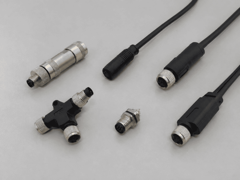
An M8 8 pin female connector can look like the right replacement on a purchasing list and still…
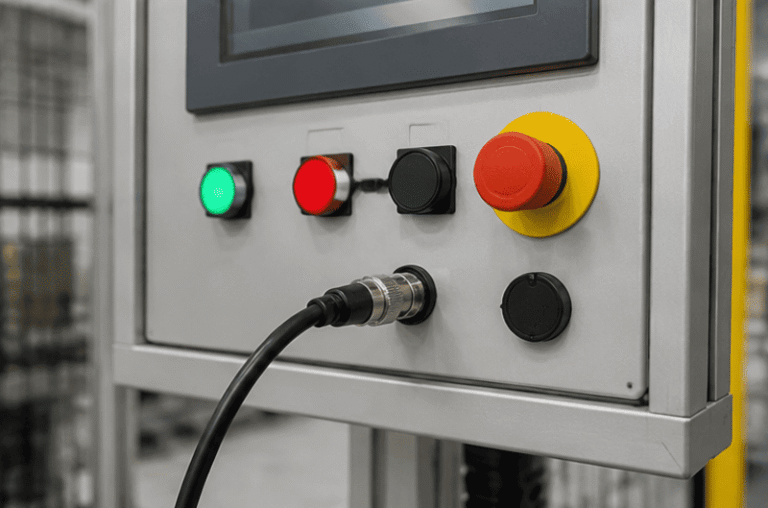
An M12 male connector 5-pin B-coded may look like a straightforward line item, but its name does not…
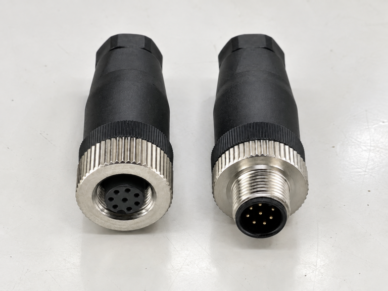
M12 connectors can carry different voltage ratings, so a buyer cannot choose one safely from the connector size…
NITAI manufactures terminal blocks, M8/M12 waterproof connectors and industrial distribution modules for global OEMs, distributors and automation customers.
Leave a Reply