Oct 17, 2026
How Do I Choose the Right M8 8 Pin Female Connector for My Equipment?
An M8 8 pin female connector can look like the right replacement on a purchasing list and still…

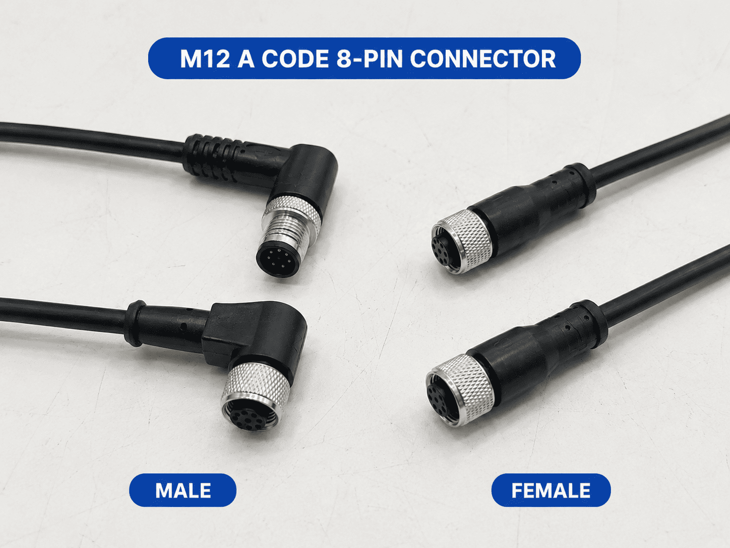
An M12 8-pin connector is not one universal connector type. The two most common versions are the A-coded 8-pin connector, used mainly for multi-signal and device-specific control connections, and the X-coded 8-pin connector, designed for four-pair Industrial Ethernet. A less common hybrid M12 interface can combine data and power contacts.
The same pin count does not guarantee mating compatibility. Before ordering an M12 8-pin cable or receptacle, you still need to confirm the coding, contact gender, viewing direction, wiring, shielding, body style, cable and equipment interface.
This guide explains those differences in the same order we use at NITAI when a customer sends us a connector photo, asks us to identify the matching male or female product and needs a sample for equipment testing.
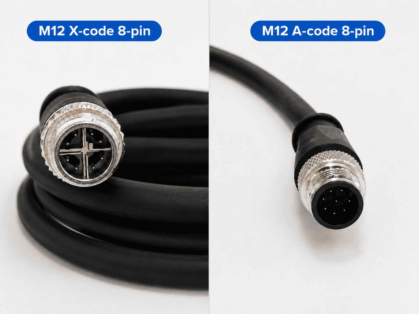
An M12 8-pin connector is a circular industrial connector with eight electrical contacts and an M12-size locking interface. The eight contacts can carry multiple control signals or four data pairs, depending on the coding and product design.
| M12 8-pin type | Primary purpose | Visual identifier | Typical cable construction | Can it mate with another 8-pin type? |
|---|---|---|---|---|
| A-coded 8-pin | Multi-signal, control, encoder and device-specific connections | A-coded keyway with eight contacts | Often unshielded for basic signals; shielded when the application requires it | Only with the corresponding A-coded mating interface |
| X-coded 8-pin | Four-pair Industrial Ethernet | X-shaped divider separates the contacts into four pairs | Category-rated data cable, normally with controlled pair construction and shielding selected for the network | Only with the corresponding X-coded mating interface |
| Hybrid data-and-power M12 | Data pairs plus power in one compact interface | Distinct hybrid insert with different contact sizes or zones | Application-specific hybrid cable | No; it is not an A-coded or X-coded substitute |
IEC 61076-2-101:2024 covers M12 screw-locking connectors from 2 to 17 positions for data, signal and power transmission, including fixed and free, rewireable and non-rewireable products.1 That broad scope is why the words “M12 8-pin” describe only part of the connector specification.
When a customer asks for an “M12 8-pin connector,” our first technical question is not whether the cable should be 2 m or 5 m. We first confirm what the connection must carry.
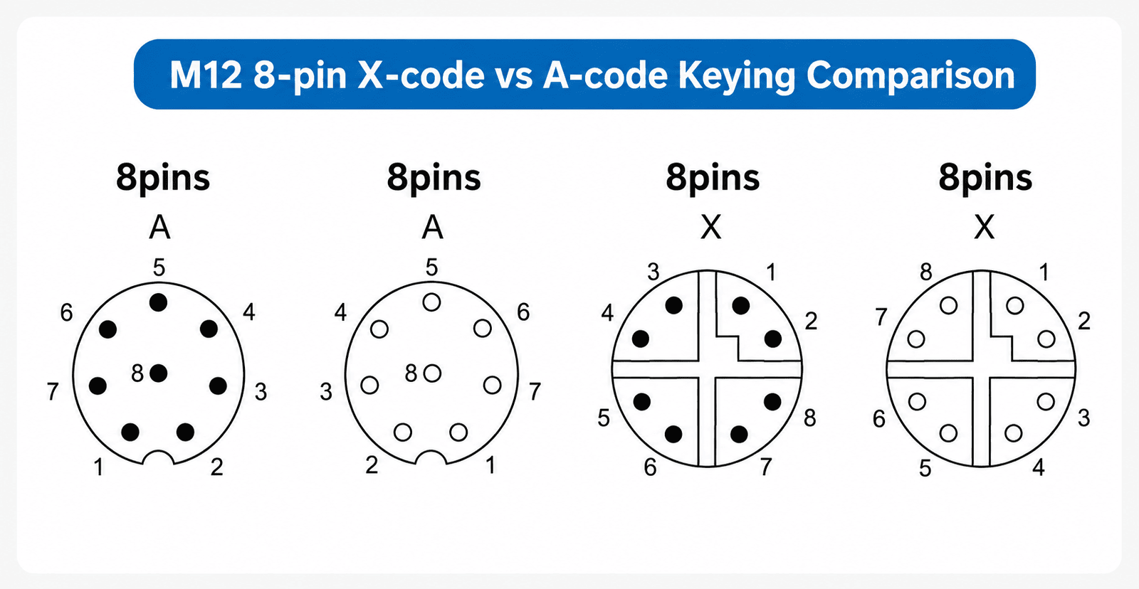
| Selection question | A-coded 8-pin | X-coded 8-pin |
|---|---|---|
| Main function | Multi-signal or device-specific control | High-speed four-pair Industrial Ethernet |
| Contact grouping | Eight contacts in an A-coded insert | Eight contacts separated into four pair zones |
| Keying | A-coded keyway | X-shaped internal divider and X-coded keying |
| Pin functions | Defined by the equipment or application | Defined by the Ethernet channel and equipment pin assignment |
| Cable | Multi-core control cable; shielded or unshielded as required | Controlled four-pair data cable appropriate for the required category |
| Shielding | Depends on signal type and EMC environment | Normally treated as part of the complete data-channel design |
| Typical mistake | Assuming the eight pins have one universal function | Selecting an X-coded head but using an unsuitable cable or shield termination |
Both products have eight contacts, but their mating faces, functions and cable requirements are different. They should never be selected by pin count alone.
An A-coded M12 8-pin connector provides more contacts than the familiar 3-, 4- or 5-pin A-coded sensor versions. It is useful when one circular interface must carry several low-voltage signals or device-specific circuits without using multiple separate connectors.
Common examples include:
The important point is that A-coded 8-pin does not define one universal pin function. Pin 1 on one encoder may have a different function from Pin 1 on another device. The connector interface can be mechanically compatible while the electrical assignment is not.
This is also why an 8-pin A-coded connector should not automatically be described as a standard IO-Link connector. The current IO-Link interface specification states that Class A ports use M5, M8 or M12 connectors with a maximum of five pins and that the M12 interfaces are mechanically A-coded.2 An A-coded 8-pin product may still appear in a machine containing IO-Link equipment, but its eight-pin assignment must come from the actual device documentation.
An X-coded M12 connector uses eight contacts arranged as four separated data pairs. The X-shaped divider is a practical visual feature and also helps improve separation between the pairs.
IEC 61076-2-109 specifies M12×1 X- and H-coded connectors for data-transmission frequencies up to 500 MHz and identifies vision systems and data acquisition among the possible applications.3
X-coded 8-pin connections are therefore commonly found in:
ODVA's physical-layer material describes the M12-8 X-coded interface as a four-pair connection designed to support transmission rates up to 10GBASE-T, with Category 6A connector performance tied to the relevant IEC and cabling requirements.4
However, an X-coded connector head alone does not guarantee a 10 Gigabit link. The complete channel also includes:
For a deeper explanation, see our guide to the M12 X-coded connector.
Yes. A customer should not assume that every eight-contact M12-style face is A-coded or X-coded.
IEC 61076-2-113 describes M12 screw-locking connectors that combine two data pairs with power contacts rated up to 12 A for industrial data-and-power applications.5 These hybrid interfaces use a different contact arrangement and must be identified from the front face and the equipment drawing.
In practice, most general inquiries we receive for “M12 8-pin” concern A-coded or X-coded products. We mention the hybrid possibility because it prevents a costly assumption when a customer sends only a side-view photo.
The front mating face provides more useful information than the outside body. Several M12 connectors can use similar metal nuts, black overmolded heads or panel housings while having completely different inserts.
Look for these four features:
| What you see | Likely interpretation | What to verify next |
|---|---|---|
| Eight contacts without the X-shaped pair divider | Often A-coded 8-pin | Keyway, equipment pinout and application |
| Eight contacts divided into four pair zones | Usually X-coded 8-pin | Network category, shielding and cable type |
| Mixed contact sizes or separate power/data zones | Possible hybrid interface | Exact standard, voltage, current and device drawing |
| Pins protruding from the insert | Male contact face | Required mating female product |
| Recessed sockets in the insert | Female contact face | Required mating male product |
If the face is dirty, damaged or photographed at an angle, ask for another image before confirming the product. A wrong assumption at this stage can lead to a sample that cannot mate at all.
M12 gender is determined by the electrical contacts—not by whether the outer shell has an internal or external-looking thread.
This sounds simple, but customers frequently send us a photo of the connector they already have and say, “I need this product.” Sometimes they actually need the matching opposite side.
We therefore confirm two separate facts:
For example, if the machine port has male pins, the cable end normally needs the corresponding female sockets with the same coding and contact arrangement. Gender alone is not enough: an A-coded female will not mate correctly with an X-coded male.
One of the most common causes of incorrect M12 wiring is using the right pin numbers from the wrong viewing direction.
A drawing may show:
Male and female front views usually appear mirrored when placed side by side. The rear wiring view may reverse the layout again. Before connecting any conductor, read the drawing label and confirm its orientation.
When we review a customer's pinout, we do not copy the pattern from a photo by eye. We align the keyway first, confirm whether the drawing is a mating-face or wiring-side view and then check each printed pin number.
An A-coded 8-pin connector has standardized mechanical geometry, but the electrical function assigned to each contact is determined by the connected device or system.
The following colors are a widely used conductor-color convention for eight-core M12 A-coded cable assemblies. They are useful for identification, but they must not replace the approved wiring drawing.
| Pin and common conductor color | Electrical function |
|---|---|
| Pin 1 — White | Device-specific—check the equipment diagram |
| Pin 2 — Brown | Device-specific—check the equipment diagram |
| Pin 3 — Green | Device-specific—check the equipment diagram |
| Pin 4 — Yellow | Device-specific—check the equipment diagram |
| Pin 5 — Gray | Device-specific—check the equipment diagram |
| Pin 6 — Pink | Device-specific—check the equipment diagram |
| Pin 7 — Blue | Device-specific—check the equipment diagram |
| Pin 8 — Red | Device-specific—check the equipment diagram |
Cable manufacturers and custom assemblies can use a different sequence. If a customer's original cable has eight colored conductors but no readable label, we recommend continuity testing from every contact to its conductor instead of relying on color alone.
For broader pin-numbering guidance, see our M12 pinout and wiring guide.
The X-coded interface divides eight contacts into four data pairs. Pair integrity is more important than simply connecting eight individual conductors in numerical order.
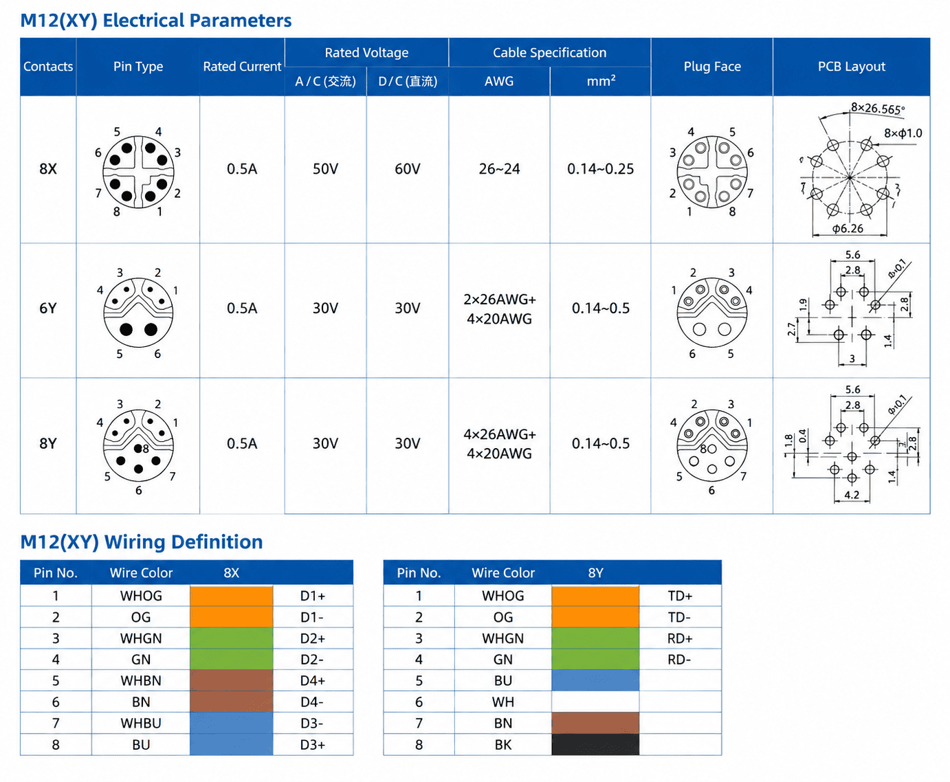
A common cable-color organization is shown below, but the final M12-to-M12 or M12-to-RJ45 map must be checked against the approved drawing.
| Contact pair | Common pair colors | Selection note |
|---|---|---|
| Pins 1–2 | White/orange and orange | Keep the pair twist and termination geometry controlled |
| Pins 3–4 | White/green and green | Do not separate the pair farther than the assembly process requires |
| Pins 5–6 | White/brown and brown | Confirm the equipment or adapter wiring map |
| Pins 7–8 | White/blue and blue | Confirm polarity and pair assignment from the drawing |
Do not use this table as a universal RJ45 conversion diagram. M12-to-RJ45 cables must be manufactured from a confirmed pin map, and the map should identify both connector views.
IEC 60512-29-100 defines M12-style connector signal-integrity tests up to 500 MHz, including insertion loss, return loss, near-end crosstalk and far-end crosstalk.6 These are channel-performance issues that cannot be verified by conductor continuity alone.
The application depends mainly on the coding and wiring—not on the number eight by itself.
| Application | Likely 8-pin type | Why eight contacts are used | Important confirmation |
|---|---|---|---|
| Encoder or feedback device | A-coded | Several power, reference and feedback conductors | Manufacturer pin assignment and signal type |
| Multi-channel sensor | A-coded | Multiple signals through one compact connector | Supply voltage, outputs and common conductors |
| Machine-vision I/O | Often A-coded | Power, trigger, strobe or control circuits | Camera manual and exact interface drawing |
| Industrial camera data | X-coded | Four-pair Ethernet transmission | Required data rate, cable category and shielding |
| Industrial switch or controller | X-coded | Rugged four-pair network connection | Port coding and supported Ethernet standard |
| Data-acquisition equipment | X-coded or device-specific A-coded | High-speed data or multiple signal channels | Equipment protocol and pinout |
| Combined data and power | Hybrid interface | Data pairs and power in one port | Hybrid coding, current, voltage and cable construction |
The connector should be treated as part of the installed industrial cabling system rather than as an isolated plug purchase. Cable construction, termination, routing and equipment ports all affect the result.
After coding and wiring are confirmed, the next question is how the product must be installed.
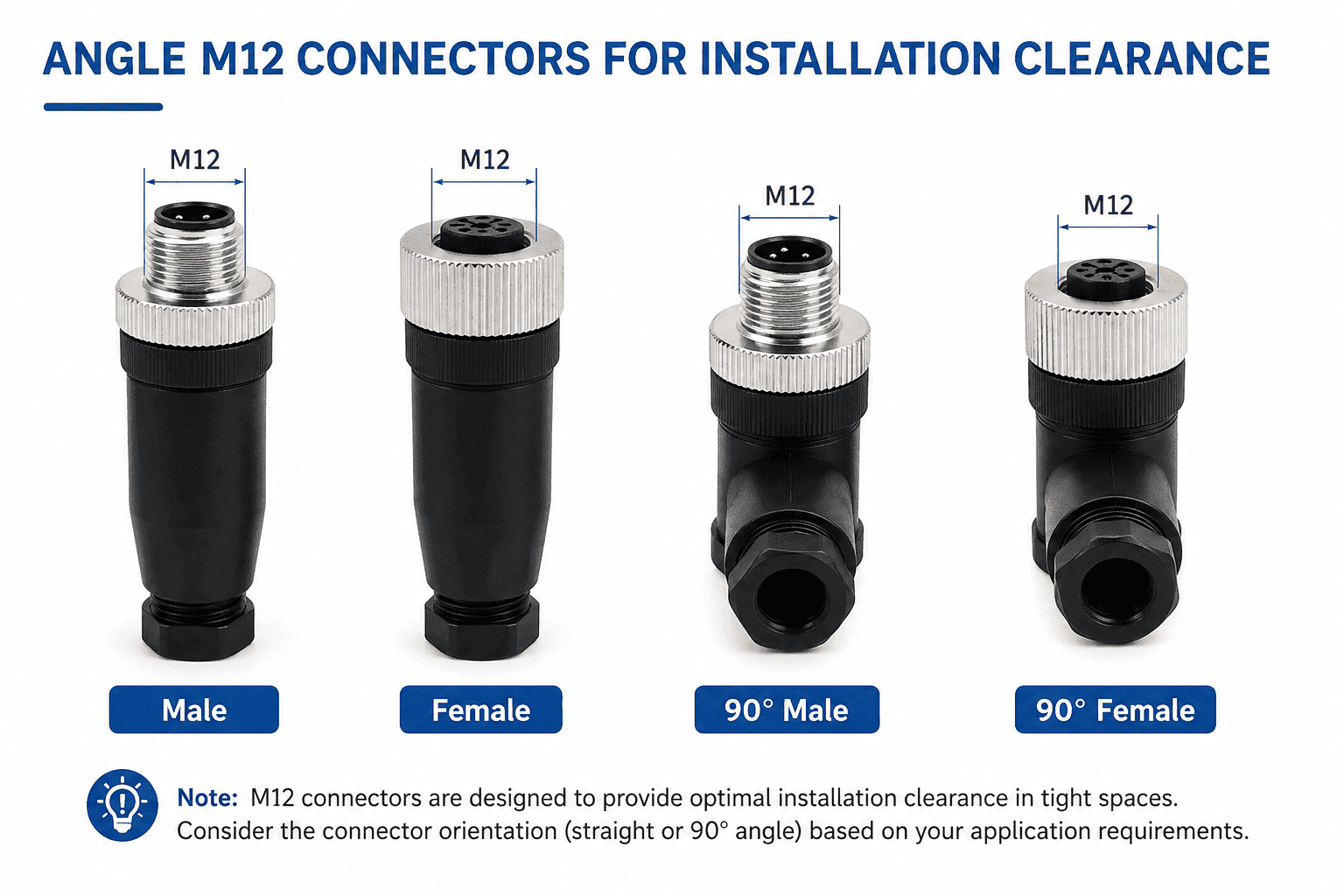
| Product type | Typical use | Main details to confirm |
|---|---|---|
| Molded cable assembly | Finished equipment cable and repeat production | Gender, coding, length, wiring, jacket and opposite end |
| Field-wireable connector | On-site installation or repair | Termination method, conductor size and cable diameter |
| Front-mount receptacle | Installation from the outside of an enclosure | Panel cutout, seal, rear thread and internal connection |
| Rear-mount receptacle | Installation from inside the enclosure | Accessible thread, panel thickness and body length |
| PCB through-hole receptacle | Direct circuit-board connection | Footprint, pin orientation and mounting height |
| SMD receptacle | Compact surface-mount equipment design | Pad layout, coplanarity and reflow requirements |
| Square-flange receptacle | Stable panel attachment | Flange dimensions, hole spacing and sealing |
| M12-to-RJ45 assembly | Industrial Ethernet transition | X-coding, pin map, category, shielding and RJ45 end |
| M12-to-M12 cordset | Equipment-to-equipment connection | Gender at both ends, orientation and straight/angled heads |
The front mating interface may follow the same M12 standard while the rear mechanical structure differs. Product length, panel thread, flange size, PCB pin position and installation height must all be checked separately.
A straight connector needs axial clearance behind the port. A right-angle connector can reduce depth and direct the cable along the machine surface.
For a right-angle product, confirm where the cable outlet points after the keyway is aligned and the connector is tightened. A right-angle head can be electrically correct but mechanically unusable if it points toward a wall, guard or adjacent port.
A molded cable assembly gives repeatable factory wiring, overmolded strain relief and a controlled sealing structure. A field-wireable connector offers on-site flexibility and adjustable cable length, but successful sealing and strain relief depend on correct assembly and an acceptable cable diameter.
For an eight-contact field-wireable product, also check whether the termination method and internal space are suitable for all eight conductors. Screw, solder, spring, crimp and IDC constructions are different product families; “field-wireable” does not mean one universal termination.
Shielding should be selected from the signal and EMC environment.
An unshielded A-coded assembly may be appropriate for ordinary low-frequency control signals when the equipment design permits it. A shielded A-coded assembly may be required for sensitive feedback, encoder or device-specific signals near motors, drives or switching equipment.
For X-coded Ethernet, consider the complete shield path:
IEC 61918 specifies installation requirements for communication-network media in industrial premises and explicitly includes balanced cabling used within and between automation islands.7 Good connector hardware cannot compensate for poor cable routing, excessive untwisting or an incomplete shield path.
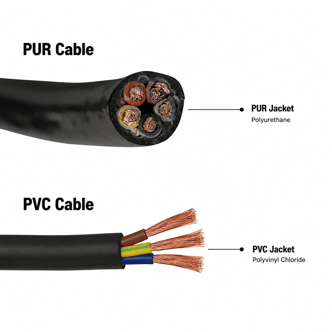
PVC and PUR describe cable-jacket materials. They do not define the connector coding, pinout or Ethernet performance by themselves.
| Cable jacket | Usually preferred for | Main advantages | Points to check |
|---|---|---|---|
| PVC | Fixed or lightly moving installations in normal industrial environments | Economical, widely available and suitable for many static applications | Temperature, oil exposure, abrasion and required approvals |
| PUR | Frequent movement, abrasion, oil exposure and demanding machine environments | Better mechanical durability in many dynamic applications | Drag-chain rating, torsion rating, chemical compatibility and cost |
We do not recommend PUR only because a customer says the connector must be waterproof. IP performance comes from the complete connector, cable-entry and sealing design. A properly designed PVC cable assembly can still be suitable for an IP67 connection, while a PUR jacket cannot correct an incorrectly assembled gland or damaged seal.
For a more detailed comparison, read What Is the Difference Between PUR and PVC Cable?.
Many M12 8-pin products are designed for industrial ingress protection, but “M12” and “8-pin” do not automatically guarantee IP67 or IP68.
The IEC explains that the first numeral in an IP code identifies protection against solid objects and the second numeral identifies protection against water.8 The rating still has to be declared and verified for the exact connector assembly and test condition.
The declared protection depends on the exact product and test condition, including:
Do not assume an unmated connector is waterproof merely because the mated assembly has an IP rating.
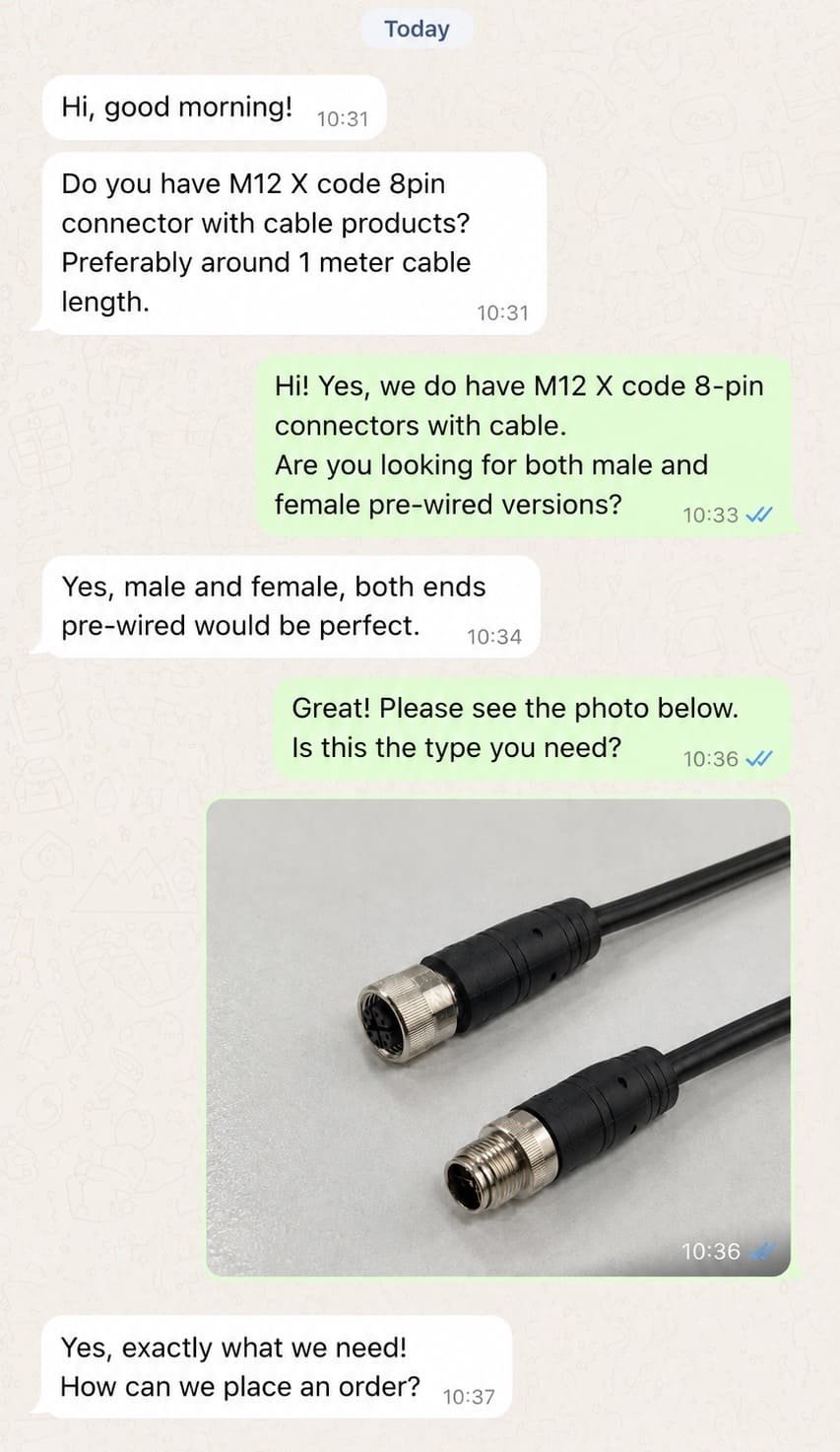
Customers often send us a photo of an existing connector and ask for the same product or a matching male or female connector. A photo is a useful starting point, but a side-view image alone is rarely enough.
| Detail | Why it matters |
|---|---|
| Eight actual contacts | Confirms the contact count and exposes blocked or special positions |
| Keyway or X divider | Distinguishes A-coded, X-coded and possible hybrid interfaces |
| Male pins or female sockets | Determines the required mating gender |
| Mating-face direction | Prevents mirrored pinout errors |
| Straight or right-angle body | Determines installation clearance and cable direction |
| Coupling and rear thread | Helps identify cable, panel or equipment-side construction |
| Cable diameter and jacket marking | Supports gland, conductor and cable-material selection |
| Product label or device model | Allows comparison with the original equipment drawing |
Sometimes a customer sends a photo of a female cable connector but actually needs the male panel receptacle that matches it. In that case, we explain the distinction, confirm the equipment-side installation and recommend the corresponding male product rather than copying the photographed part.
If the connector face is clear but the rear structure is hidden inside the machine, we may still need the panel opening, thread size, PCB footprint or original drawing. A standard front interface does not guarantee that the rear dimensions will fit.
We use the following sequence for replacement products and custom cable assemblies.
We ask whether the connection carries multi-signal control, encoder feedback, Industrial Ethernet or combined data and power. The device protocol often narrows the coding immediately.
We examine the front face, keyway, divider and contacts. We then confirm whether the customer wants the photographed connector or its mating counterpart.
We compare the equipment drawing with the proposed connector drawing. Every pin function, conductor color and drawing view must be unambiguous.
We confirm straight or angled, molded or field-wireable, cable or panel mount, front or rear mount, PCB or solder, body length and installation dimensions.
We review cable length, conductor size, PVC or PUR, shielding, fixed or moving use, temperature, oil exposure and required IP performance.
For custom assemblies, the approved drawing should show both connector ends, pin mapping, cable specification, length, orientation and any label or open-end treatment.
The sample allows the customer to verify mating, wiring, communication, installation clearance and operation on the real equipment.
After the sample is approved, the confirmed drawing and sample configuration become the basis for mass production and inspection.
A photograph can confirm many visible features, and a drawing can confirm dimensions and wiring. Neither proves that the complete assembly works in the customer's equipment.
A sample test can reveal:
For a standard repeat order with an approved drawing, another sample may not be necessary. For an unknown replacement, new equipment design or custom M12-to-RJ45 cable, sample confirmation can prevent a much larger production problem.
Before requesting a quotation, confirm as many of the following items as possible.
X-coded and hybrid eight-contact interfaces exist. Count the contacts, then identify the coding.
They use different keying and contact structures. Matching pin count does not make them compatible.
Colors help identify conductors, but device functions must come from the approved wiring diagram.
Male, female, mating-face and wiring-side drawings can appear mirrored. Label the view before assigning conductors.
Network performance depends on the complete four-pair channel, not the connector name alone.
The coding and pin arrangement are on the front face. The rear structure and dimensions determine whether it fits the equipment.
Clarify whether the customer wants a replacement of the pictured connector or the connector that plugs into it.
Check the exact product rating, mating state, seal, cable range and installation instructions.
A sample is the safest way to verify mating, wiring, clearance and actual device operation.
No. A-coded, X-coded and hybrid M12 interfaces can all involve eight contacts, but they use different mating structures and serve different applications. Gender, wiring, body style and cable construction can also differ.
An A-coded 8-pin connector is generally used for multi-signal or device-specific control connections. An X-coded 8-pin connector separates the contacts into four pairs for higher-speed Industrial Ethernet. They cannot be used as direct substitutes.
No. Their keyways and contact structures are designed to prevent incompatible mating.
No. X-coded 8-pin products are used for four-pair Industrial Ethernet, while A-coded 8-pin products are often used for multiple signals, feedback or device-specific wiring.
The mechanical interface and pin numbering follow the relevant connector design, but an A-coded connector does not have one universal device-function assignment. X-coded Ethernet assemblies also require an approved pair and signal map. Always use the equipment manual or project drawing.
A common A-coded eight-core sequence is white, brown, green, yellow, gray, pink, blue and red for Pins 1 through 8. X-coded data cables commonly use four color-coded twisted pairs. Actual colors and assignments must be verified from the cable and assembly drawing.
An appropriately designed X-coded M12 interface can be used in a Category 6A four-pair channel supporting 10GBASE-T. The connector, cable, terminations, link length and devices must all meet the required performance; the words “8-pin” alone do not establish the data rate.
Not necessarily. Many ingress-protection ratings apply when the connector is correctly assembled, fully mated and tightened. Unused or disconnected interfaces may require a suitable protective cap.
PVC is usually the economical choice for normal fixed installations. Application-rated PUR is generally preferred when the cable faces frequent movement, abrasion, oil or demanding mechanical conditions. Choose from the real environment rather than from the connector's pin count.
Send clear photos of the front mating face, side, rear connection and label. Also provide the device model, dimensions, application and any available wiring diagram. These details allow the coding, gender, construction and likely matching product to be checked.
Yes. After the interface, wiring, dimensions and cable requirements are confirmed, we can prepare the corresponding mating product or custom assembly for sample testing before mass production.
The safest way to select an M12 8-pin connector is to treat “8-pin” as the starting point, not the complete specification.
First determine whether the application needs an A-coded multi-signal connection, an X-coded four-pair Ethernet connection or a hybrid data-and-power interface. Then confirm gender, mating-face view, pin assignment, shielding, body style, cable and installation dimensions.
If you already have a male or female connector but do not know the model, send NITAI clear photos of the mating face, side and rear, together with the equipment model and wiring information. We can help identify the existing interface, recommend the corresponding mating connector, confirm the drawing and prepare a sample for testing.
Browse our M12 connector product range or contact NITAI with your photos, required quantity and application details.
International Electrotechnical Commission, IEC 61076-2-101:2024, detail specification for M12 screw-locking connectors from 2 to 17 positions. ↩
IO-Link Community, IO-Link Interface and System Specification Version 1.1.4, connector requirements for Class A and Class B ports. ↩
International Electrotechnical Commission, IEC 61076-2-109:2014, M12×1 connectors for data transmission up to 500 MHz. ↩
ODVA, Recent Changes to the Physical Layer for EtherNet/IP, M12-8 X-coding and Category 6A channel-performance information. ↩
International Electrotechnical Commission, IEC 61076-2-113:2017, M12 hybrid connectors with two data pairs and power contacts. ↩
International Electrotechnical Commission, IEC 60512-29-100:2015, signal-integrity tests up to 500 MHz for M12-style connectors. ↩
International Electrotechnical Commission, IEC 61918:2018 with amendments, installation of communication networks in industrial premises. ↩
International Electrotechnical Commission, IP Ratings, explanation of the two numerals in an ingress-protection code. ↩
An M8 8 pin female connector can look like the right replacement on a purchasing list and still…

An M12 male connector 5-pin B-coded may look like a straightforward line item, but its name does not…
M12 connectors can carry different voltage ratings, so a buyer cannot choose one safely from the connector size…
NITAI manufactures terminal blocks, M8/M12 waterproof connectors and industrial distribution modules for global OEMs, distributors and automation customers.
Leave a Reply