Oct 17, 2026
How Do I Choose the Right M8 8 Pin Female Connector for My Equipment?
An M8 8 pin female connector can look like the right replacement on a purchasing list and still…

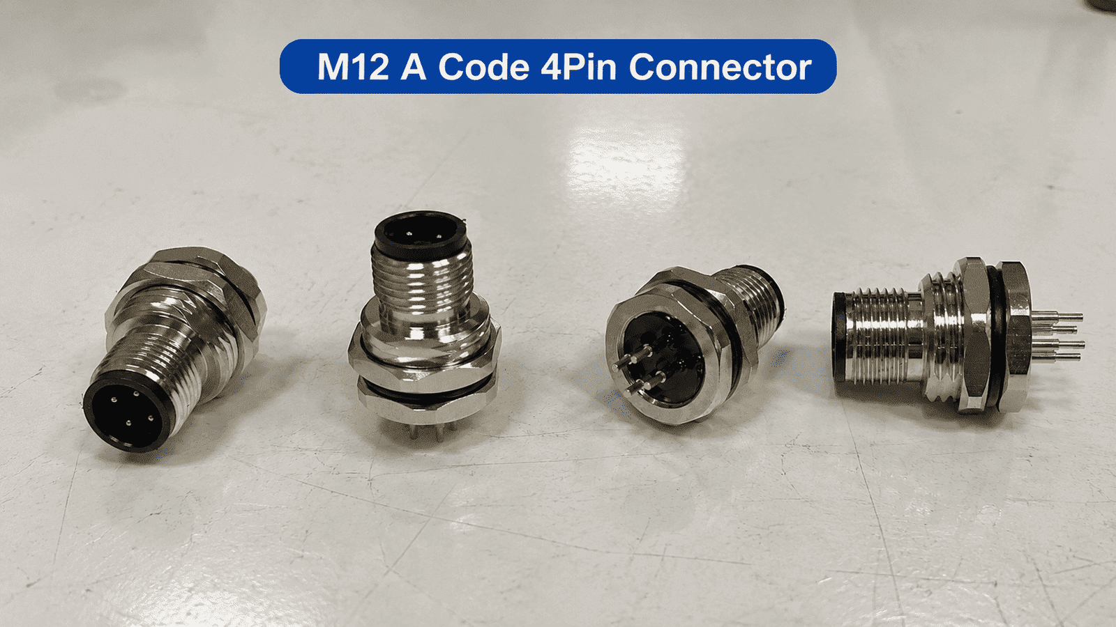
M12 connector types are not defined by one feature alone. A complete M12 connector description may include its coding, pin count, contact gender, body style, mounting method, termination, shielding, cable material and locking mechanism.
For example, “M12 4-pin connector” is not a complete part description. It could mean an A-coded sensor connector, a D-coded Industrial Ethernet connector, a molded cable assembly, a field-wireable plug or a panel-mount receptacle. These products may look similar from the side, but they are not necessarily interchangeable.
This guide organizes the M12 family in the same order we use when helping customers identify an existing connector or select a new cable assembly.
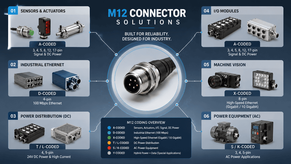
M12 connectors can be grouped in several ways:
| Selection dimension | Common M12 connector types | What it determines |
|---|---|---|
| Application and coding | A, B, C, D, X, S, T, K, L and other codings | Intended signal, data or power system and mating compatibility |
| Pin count | 2, 3, 4, 5, 6, 8, 12, 17 and other coding-specific arrangements | Number and arrangement of electrical contacts |
| Contact gender | Male pins or female sockets | Which contact face mates with the device or cable |
| Body direction | Straight or right-angle | Cable exit direction and installation clearance |
| Product construction | Molded, field-wireable, panel-mount, PCB-mount or adapter | How the connector is installed and terminated |
| Mounting style | Front mount, rear mount, bulkhead, flange or direct PCB mount | Mechanical fit with the enclosure or circuit board |
| Termination | Prewired, screw, spring, solder, crimp or IDC | Assembly process and serviceability |
| EMC construction | Shielded or unshielded | Suitability for data transmission and electrically noisy areas |
| Cable jacket | PVC, PUR or application-specific compound | Cost, flexibility, abrasion resistance and environmental durability |
| Locking method | M12 screw locking or a compatible push-pull interface | Connection speed, retention and equipment interface |
The right type is the combination of these features that matches the device—not the connector with the highest specification.
“M12” identifies an interface family, not one universal plug. The name refers to the nominal metric thread used by the traditional screw-locking interface. IEC metric connector families are named for thread sizes such as M5, M8 and M12, while coding further defines the contact layout, mating-face shape and electrical properties.1
The current connector standards also cover more than one physical construction. IEC 61076-2-101:2024 describes screw-locking M12 connectors from 2 to 17 positions and includes fixed and free connectors in both rewireable and non-rewireable forms.2
This is why two products can both be described as “M12” while differing in almost every detail that matters to the application.
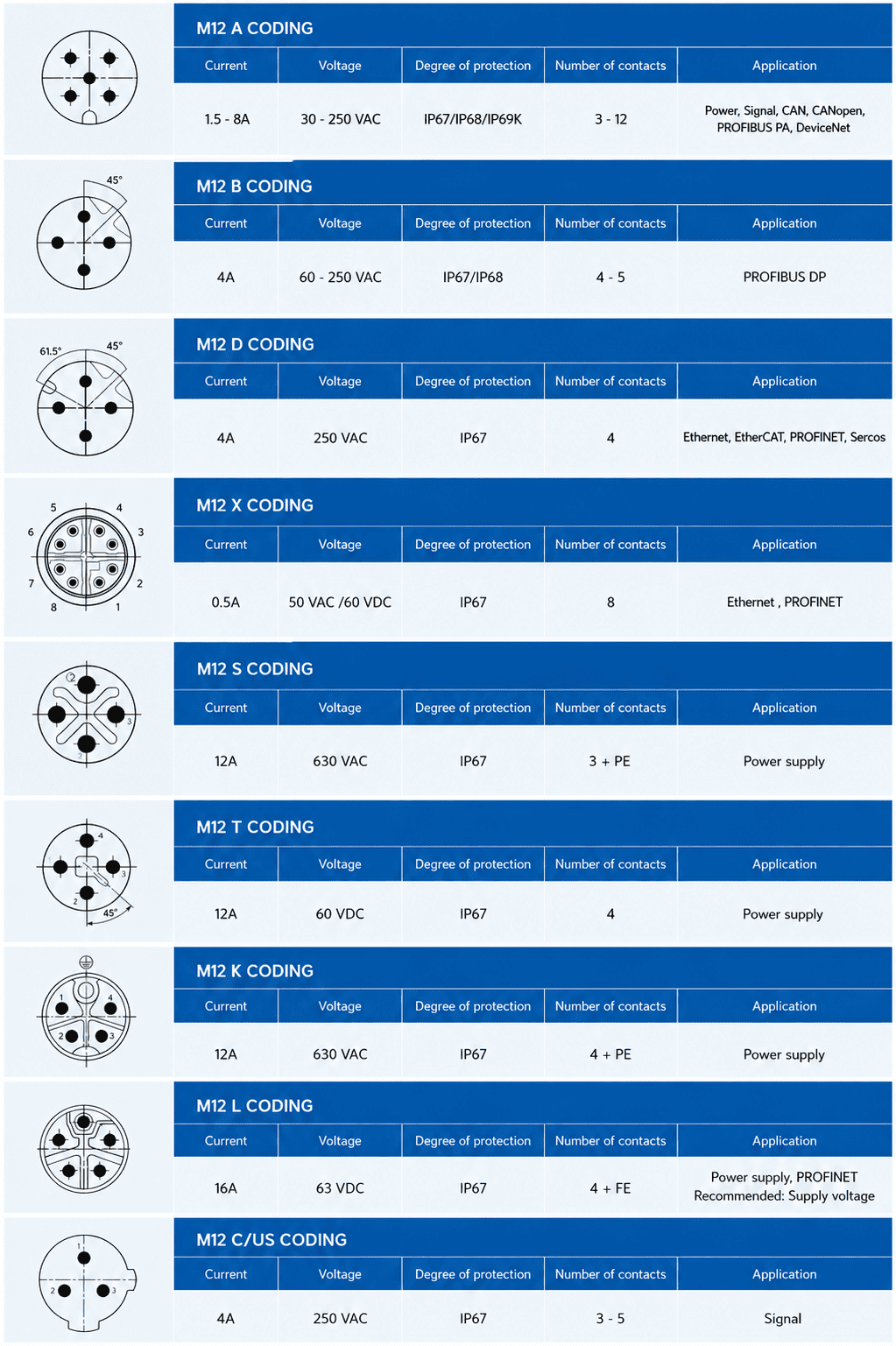
Coding is usually the first technical filter. Each coding uses a defined keyway or mating-face geometry to help prevent incompatible connectors from being plugged together.
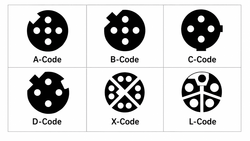
| Coding | Common contact arrangement | Typical use | Important selection note |
|---|---|---|---|
| A-coded | Commonly 3, 4, 5, 8 or 12 contacts; other standardized arrangements exist | Sensors, actuators, IO-Link, control signals and low-voltage connections | Never assume every A-coded device uses the same pin function |
| B-coded | Commonly 5 contacts | PROFIBUS and selected fieldbus systems | Similar outside appearance does not make it compatible with A-coded products |
| C-coded | Coding-specific power arrangements | AC power and older industrial power applications | Verify voltage, current, protective-earth arrangement and equipment standard |
| D-coded | 4 contacts | 100 Mbps Industrial Ethernet, including common PROFINET and EtherNet/IP installations | Do not confuse it with a 4-pin A-coded sensor connector |
| X-coded | 8 contacts in four separated pairs | Higher-speed Industrial Ethernet, machine vision and data acquisition | The entire cable channel must support the required category and bandwidth |
| S-coded | Power-contact arrangement with coding-specific PE options | AC power | Ratings depend on the exact connector design and applicable standard |
| T-coded | Coding-specific DC power arrangement | DC power distribution | Confirm polarity, voltage and current before ordering |
| K-coded | Power contacts with protective earth | Higher-power AC applications | Cable size, contact rating and thermal conditions must be checked together |
| L-coded | Coding-specific DC power arrangement | Compact DC power distribution | Confirm the required FE/PE option and device-side interface |
This table is a selection map, not a substitute for the device drawing. The same coding can have more than one contact arrangement, and the allowed electrical rating changes with the exact design.
A-coded M12 connectors are widely used for sensors, actuators, control signals and IO-Link devices. In many automation projects, a 4-pin or 5-pin A-coded connector is the first product people picture when they hear “M12 connector.”
The IO-Link system description shows M12 connections used in IP65/IP67 field environments and illustrates typical sensor, actuator and master-port arrangements.3 However, an A-coded mating face alone does not tell you the device’s complete wiring assignment. Always compare the pin numbers with the equipment manual.
D-coded M12 connectors are commonly selected for two-pair Industrial Ethernet links. Their rugged circular form and threaded locking are useful on factory equipment where a standard office-style connector may not provide the desired retention or environmental protection.
The critical identification point is the keyway. A 4-pin D-coded connector and a 4-pin A-coded connector are not alternatives simply because both have four contacts.
An X-coded mating face normally has an X-shaped internal divider that separates eight contacts into four data pairs. IEC 61076-2-109 specifies M12×1 connectors for data frequencies up to 500 MHz and identifies vision systems and data acquisition among the intended applications.4
Choosing an X-coded connector does not automatically make the complete connection high speed. The cable category, pair twist, shielding, shield termination, cable length, equipment ports and installation environment must all support the target network performance. Our detailed guide to the M12 X-coded connector explains this complete-channel requirement.
Power codings such as S, T, K and L exist because signal, network and power interfaces require different contact arrangements and protection against mismating. Do not select a power connector from coding name alone. We confirm:
Power ratings should always come from the exact product drawing and relevant test data, not from a generic M12 comparison chart.
M12 connectors do not have a fixed number of pins. Common products include 2-, 3-, 4-, 5-, 6-, 8-, 12- and 17-position versions, but the available pin count depends on the coding and product standard.
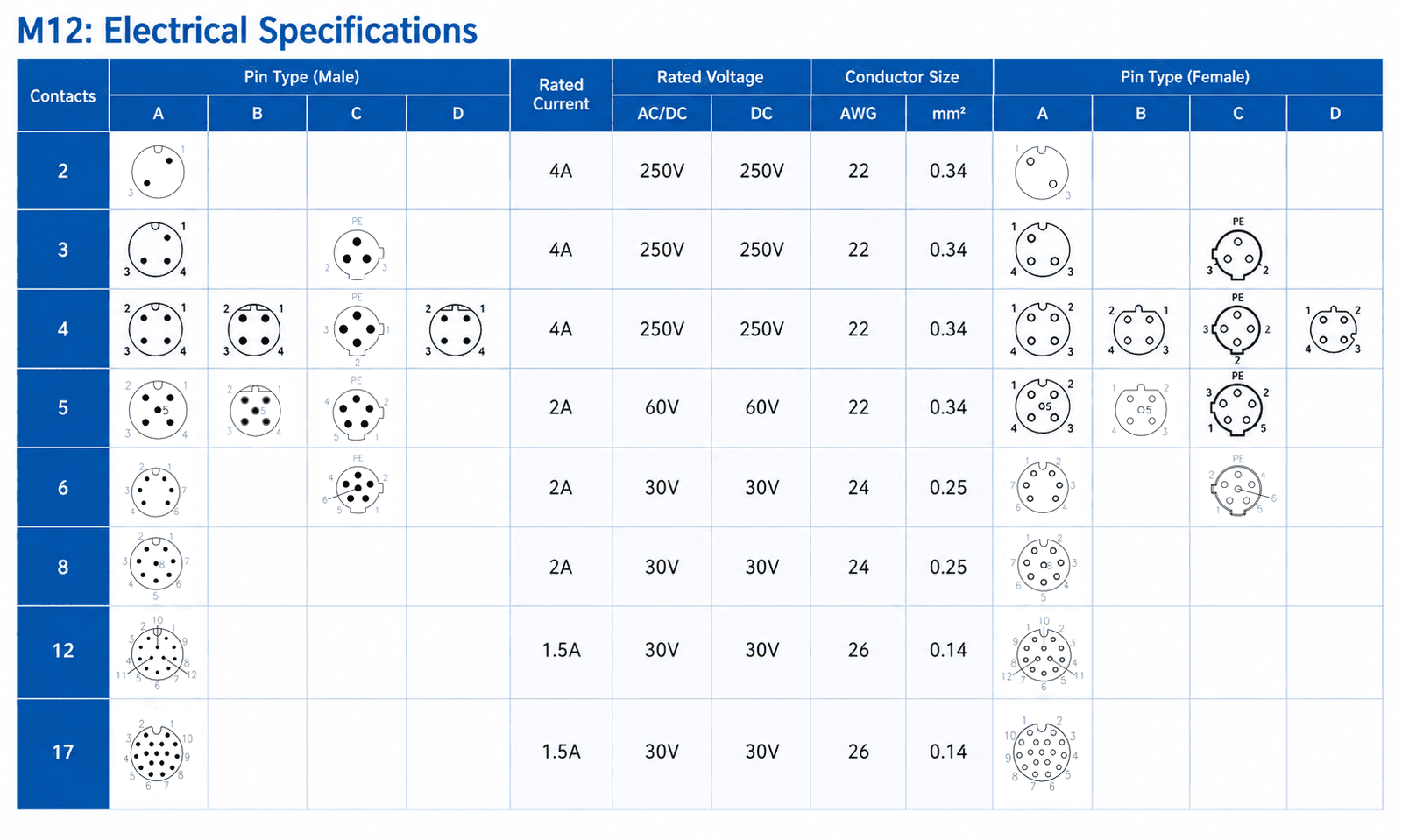
| Pin count | Common examples | What still needs confirmation |
|---|---|---|
| 2 or 3 | Selected signal or power connections | Coding, polarity, PE/FE and electrical rating |
| 4 | A-coded sensors, D-coded Ethernet and selected power arrangements | Coding is essential because the products may not mate |
| 5 | A-coded sensors and actuators, B-coded fieldbus | Keyway, wiring and application |
| 6 | Multi-signal and application-specific A-coded connections | Exact insert arrangement and device drawing |
| 8 | A-coded multi-signal or X-coded Ethernet | Coding, shielding and cable construction |
| 12 or 17 | High-density signal and control connections | Insert layout, current per contact and wiring map |
“I need an M12 4-pin connector” is one of the most common inquiries we receive, but it is only the beginning of selection. A 4-pin count does not tell us whether the customer needs a sensor cordset, an Ethernet cable, a panel receptacle or a power interface.
If wiring is the main question, use our M12 A-coded pinout guide and confirm the viewing direction before connecting conductors.
M12 gender is determined by the electrical contacts:

Do not identify gender only from the metal thread or coupling nut. Cable connectors and equipment receptacles can use different shell arrangements while retaining the same contact gender.
Another common source of error is viewing direction. A male and female mating face may appear mirrored when both are viewed from the front. A wiring-side drawing may also look different from a mating-face drawing. We therefore ask whether a photo or diagram shows:
When a customer needs a matching male or female connector, a clear, straight-on photo of the existing mating face is much more useful than a distant side photo.
The same coding and pin count may be available in several mechanical formats.
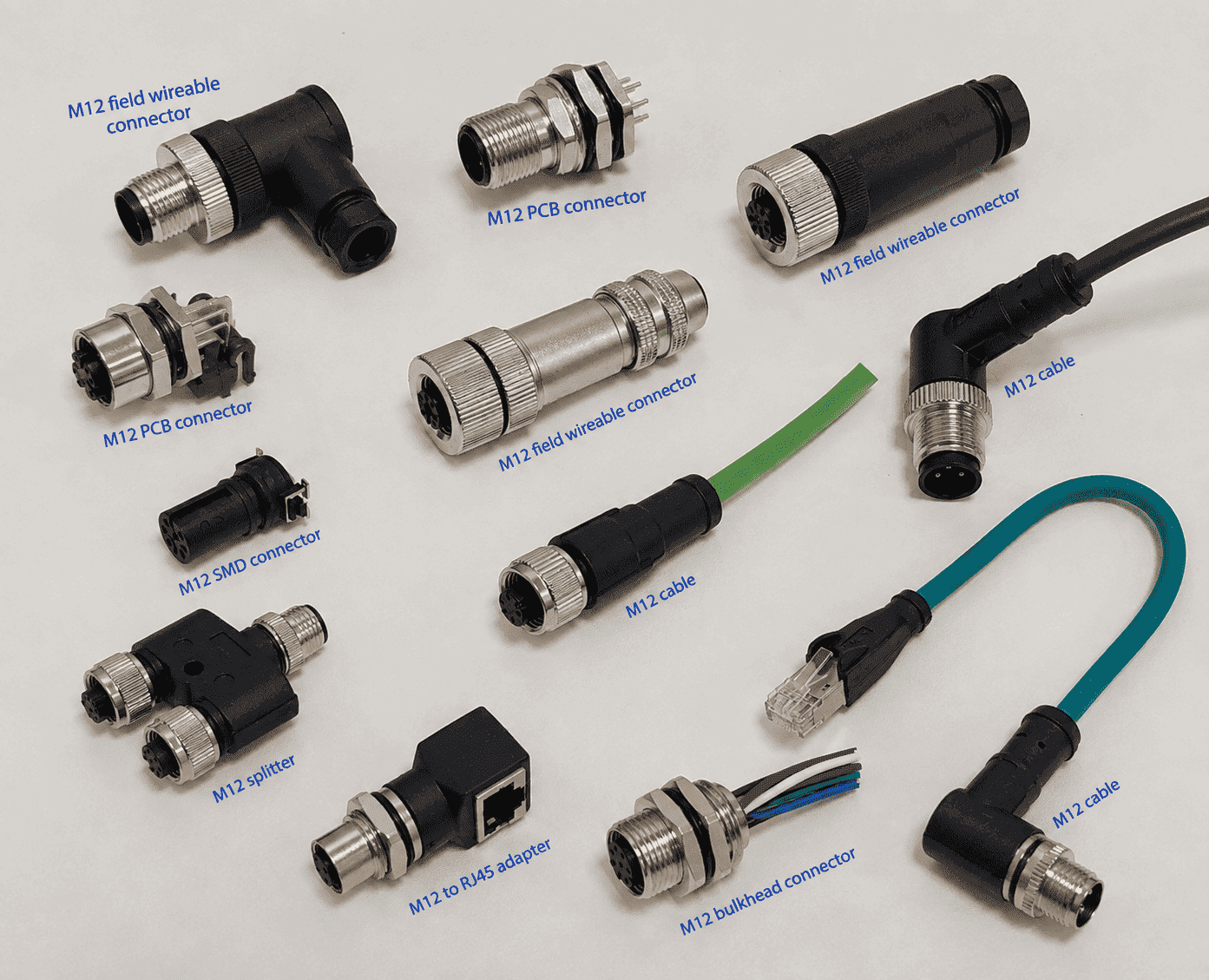
| Construction type | How it is installed | Best suited for | Main details to confirm |
|---|---|---|---|
| Molded cable assembly | Connector is overmolded onto a finished cable | Factory-built cordsets and repeat production | Cable material, length, wiring, shield and opposite end |
| Field-wireable connector | Cable is terminated during installation | Site installation, repair and adjustable cable length | Conductor size, cable diameter, termination and assembly IP rating |
| Panel-mount receptacle | Connector is fixed to an enclosure or equipment panel | Machines, I/O boxes, controllers and sensors | Front/rear mounting, thread, panel cutout, leads and sealing |
| PCB-mount receptacle | Contacts connect directly to the circuit board | Compact equipment and device ports | Footprint, orientation, body height and enclosure clearance |
| Adapter or transition cable | Two different interfaces are connected | Network conversion, extension and equipment integration | Coding and pin map at both ends |
A molded connector is permanently overmolded onto the cable. It is usually the best choice for repeatable factory assembly, reliable strain relief and a controlled sealing structure.
Typical options include:
Field-wireable connectors allow installation or repair on site. Depending on the design, termination may use screws, springs, solder, crimp contacts or insulation-displacement technology. It is incorrect to assume that every field-wireable M12 connector uses screw terminals.
Before selecting one, check the accepted conductor size, cable outer diameter, shielding method, assembly tooling and achievable ingress protection after assembly.
Panel receptacles are installed on equipment housings, junction boxes, sensors, controllers and I/O modules. Variants may include:
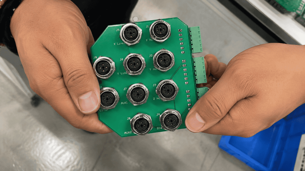
The front mating interface may be standardized, but the rear thread, flange, body length, panel cutout, sealing method and PCB footprint are not automatically identical across manufacturers. A connector that mates correctly at the front can still fail to fit the customer’s panel or board.
PCB-mounted receptacles can use through-hole or surface-mount contacts, depending on the product. Selection should be based on the manufacturer’s dimensioned drawing and recommended footprint. For an existing PCB, we ask for the board-hole pattern, pin spacing, orientation, standoff height and available enclosure clearance.
Common transition products include M12-to-RJ45 Ethernet cables, M12-to-M8 adapters, panel feedthroughs and coding-specific extension cables. Both ends must be specified independently; “M12 to RJ45” does not define the M12 coding, network category, shielding or pin map.
A straight connector is usually easier to route when there is enough axial space. A right-angle connector can reduce required depth and direct the cable along the machine surface.
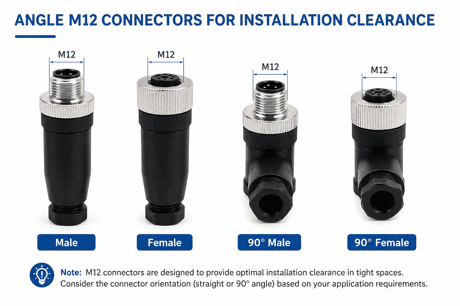
For right-angle products, check the cable-outlet direction relative to the keyway. Two right-angle connectors with the same coding and pin count may point in different directions after the device port is tightened. A photo of the installation area or a simple orientation sketch can prevent an expensive mechanical mismatch.
The familiar M12 connection uses an M12×1 screw-locking mechanism, but standardized push-pull variants also exist. IEC 61076-2-010 defines push-pull interfaces derived from M12 screw-locking systems and explains which correspondingly coded screw-locking free connectors can mate with the specified fixed push-pull interfaces.5
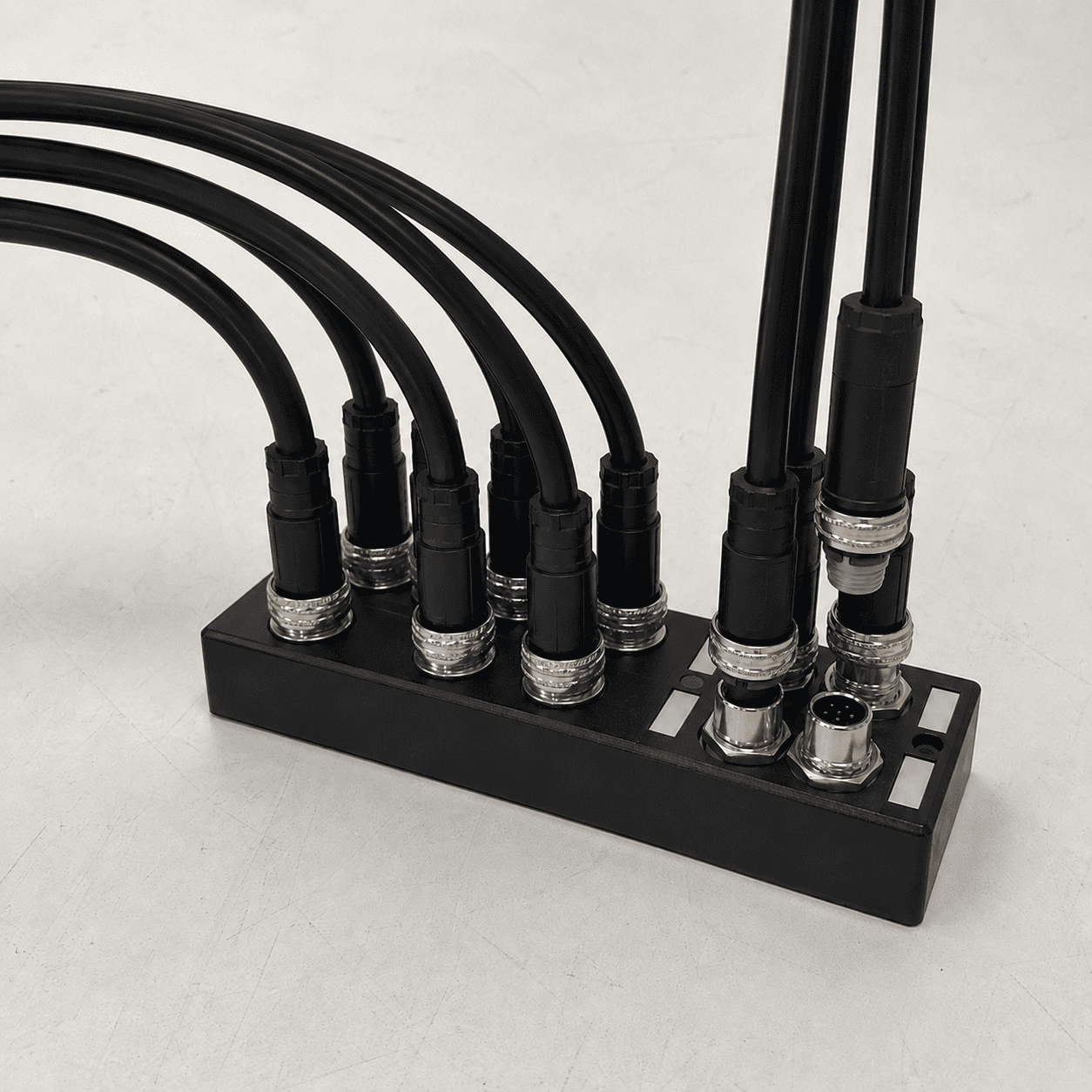
This does not mean every product advertised as “M12 push-pull” is universally compatible. Confirm the exact standard, inner or outer locking design, fixed or free connector, coding and equipment interface.
Unshielded M12 assemblies are often sufficient for basic sensor power and switching signals. Shielded construction is normally considered for Industrial Ethernet, high-frequency signals and installations with significant electromagnetic interference.
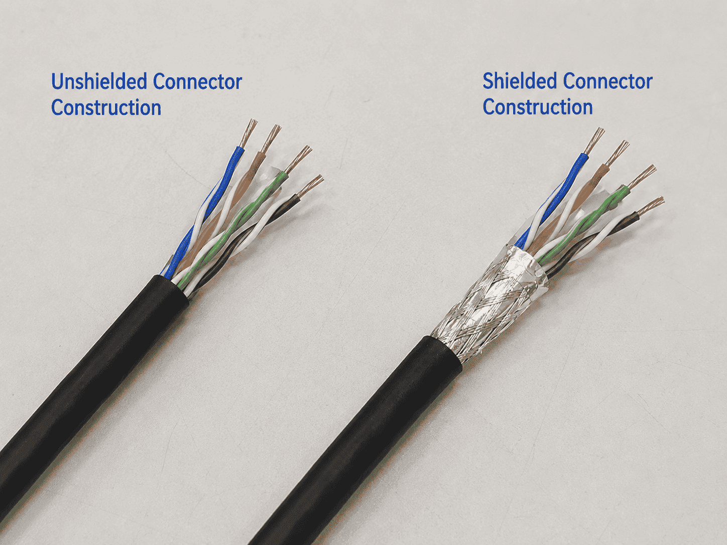
For a shielded assembly, the connector body alone is not enough. Performance also depends on:
The official PROFINET cabling guide treats connectors, cable, installation and channel verification as parts of one cabling system rather than isolated components.6 We use the same complete-link approach when recommending D-coded or X-coded assemblies.
Cable material is another M12 connector type decision, especially for molded cordsets.
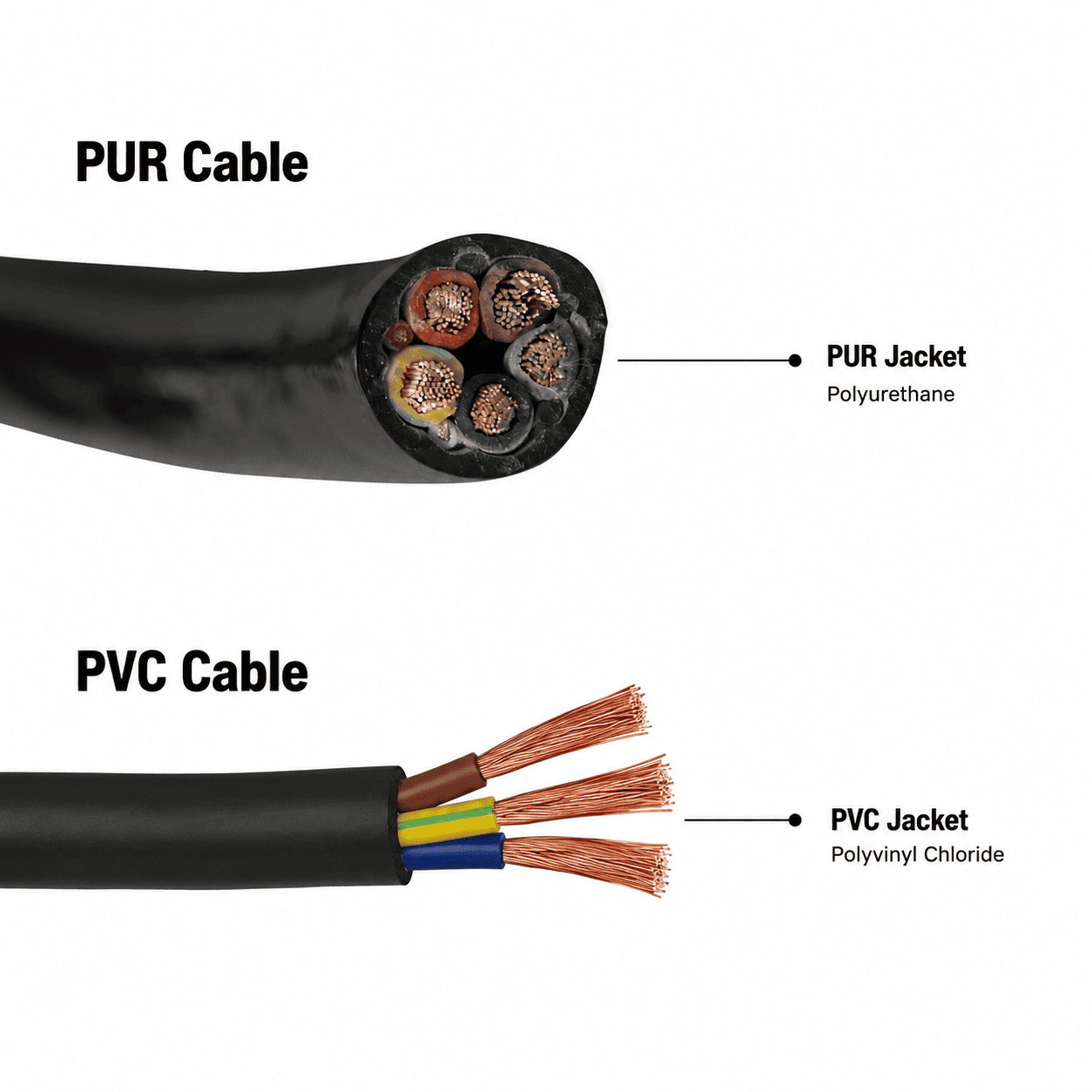
| Application condition | PVC cable | PUR cable |
|---|---|---|
| Fixed or low-movement installation | Often the more economical choice | Suitable, but may add unnecessary cost |
| Frequent bending or repeated movement | Limited unless the specific cable is designed for it | Usually the better match when dynamically rated |
| Abrasion and mechanical wear | Moderate, depending on formulation | Commonly selected for higher abrasion resistance |
| Oil exposure | Product-specific | Often preferred for demanding oily industrial environments |
| Customer budget | Lower-cost options are widely available | Usually more expensive |
We do not automatically recommend PUR because its specification sounds higher. If the cable is fixed, the environment is normal and repeated dragging is not expected, a suitable PVC assembly can be more economical and fully adequate. If the cable must bend frequently, run in a drag chain, resist abrasion, move repeatedly or remain exposed to oil, we are more likely to recommend an application-rated PUR cable.
Ingress protection is not determined by the jacket material alone. It depends on the complete mated connection, seals, cable entry and assembly quality. The IEC explanation of IP ratings confirms that the two rating digits classify protection against solid objects and liquids.7 The product’s stated IP rating and test conditions should be checked for the assembled, properly mated system.
Customers often send us a photo and ask, “Can you match this connector?” In many cases, a photo is a very good starting point—but one side-view image is rarely enough for a safe recommendation.
Please send:
We look for:
The mating face is usually more important than the outside shell. Several M12 connectors can look almost identical from the side while using different keyways or contact arrangements.
In real inquiries, customers do not always begin with a complete part number. They may have a machine port, a male or female connector that needs a mate, an old cable with no readable label, or only a photo supplied by their own end customer.
Our process is practical:
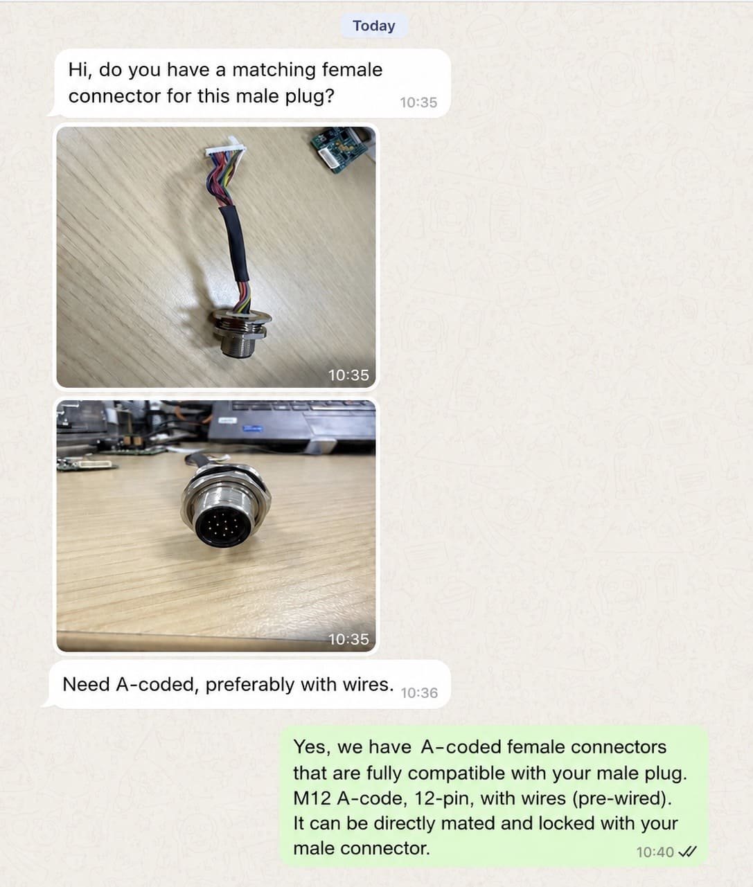
We first determine whether the customer is showing us the existing product or the connector that must mate with it. Then we examine contact gender, coding, pin count, body style and visible mechanical features.
If the photo is not enough, we ask for additional information instead of guessing. This may include:
The IO-Link Design Guideline similarly emphasizes determining the connector used by the device and checking the applicable device documentation.8 A standard family name should never replace verification of the actual port.
Once the interface and application are clear, we recommend the most suitable standard product or cable assembly. We confirm the connector face, dimensions, wiring, cable specification and opposite end in a drawing before production.
If a standard PVC assembly can meet the operating conditions and budget, we will say so. If frequent motion, abrasion, oil or service-life requirements justify PUR, we explain why the higher-cost material is a better match. Our goal is not to select the cheapest or most expensive option; it is to balance compatibility, reliability and cost.
For a new design or an uncertain replacement, we recommend confirming a sample before mass production. The customer can then check:
Sample feedback may lead to small but important changes, such as cable length, cable color, wire color, label, connector height or right-angle outlet direction. If the sample works without changes, the confirmed sample and drawing become the reference for the production order.
This photo-to-sample process takes more communication than choosing from a generic chart, but it greatly reduces the risk of ordering an M12 connector that looks right and still does not fit.
Before requesting a quotation, answer as many of these questions as possible:
For a broader explanation of how M12 is used in automation, see What Is an M12 Connector Used For?. For a focused comparison of keyways, see our M12 connector coding guide.
A 4-pin A-coded connector and a 4-pin D-coded connector serve different purposes and do not share the same mating interface.
The body may look familiar while the front insert, keyway or pin arrangement is different. Ask for a mating-face photo.
Male and female refer to pins and sockets. Confirm the contact face instead of judging only by the shell.
A standard M12 front interface does not guarantee that the panel thread, body length or PCB layout will match the existing product.
The connector, cable, shielding, termination, length and device ports form one link. X-coded hardware paired with an unsuitable cable will not deliver the expected performance.
Water resistance depends on the complete mated and assembled system. PVC and PUR assemblies can both be designed for protected connections when the connector and sealing structure are suitable.
A dimensional drawing reduces risk, but an actual sample confirms mating, installation clearance, wiring and use on the real equipment.
A-coded 4-pin and 5-pin connectors are among the most familiar types in sensor and actuator applications. However, the most appropriate type depends on the equipment interface and what the connection carries.
No. The coding, contact arrangement, gender and mechanical interface must match. Even when the mating face is compatible, the rear mounting dimensions, wiring and electrical rating may differ.
No. Male and female contact gender is only one condition. Coding, pin count, insert arrangement and applicable interface standard must also match.
No. Four-contact products exist in more than one coding and application family. D-coded Industrial Ethernet is a common example that must not be confused with A-coded sensor wiring.
The standardized X-coded M12 data interface uses eight contacts arranged as four separated pairs. If a product description calls a different arrangement “X-coded,” request the mating-face drawing and applicable standard before ordering.
Sometimes, but a reliable match usually requires a front mating-face photo plus gender, pin count, dimensions and application information. A device model or original drawing makes confirmation much easier.
Choose molded assemblies for repeatable factory-built strain relief and sealing. Choose field-wireable products when on-site installation, repair or adjustable cable length is more important. Confirm the termination method and cable range.
PVC is often the economical choice for normal fixed installations. Application-rated PUR is usually more suitable for frequent movement, abrasion, dragging and demanding oily environments. Select from the real duty cycle and budget.
The best way to understand M12 connector types is to treat the product as a combination of decisions: coding, contacts, gender, body, mounting, termination, shielding and cable.
If you already have a connector but do not know its exact model, send NITAI clear photos of the mating face, side and rear, together with the equipment model and application details. We can help identify what you have, determine whether you need a matching male or female product, confirm the drawing and prepare a sample for testing before volume production.
Contact NITAI with your photos, required quantity and operating conditions, or browse our M12 connector product range.
Wikipedia, [IEC metric screw sized connectors](https://en.wikipedia.org/wiki/IEC_metric_screw_sized_connectors), overview of M-series naming, coding and keyways. ↩
International Electrotechnical Commission, [IEC 61076-2-101:2024](https://webstore.iec.ch/en/publication/77773), detail specification for M12 screw-locking connectors. ↩
IO-Link Community, [IO-Link System Description](https://io-link.com/fileadmin/user_upload/Downloads/About_IO-Link/IO-Link_System_Description_eng_2018.pdf), connector and port examples for sensors, actuators and field installations. ↩
International Electrotechnical Commission, [IEC 61076-2-109:2014](https://webstore.iec.ch/en/publication/4425), M12×1 connectors for data transmission up to 500 MHz. ↩
International Electrotechnical Commission, [IEC 61076-2-010:2021](https://webstore.iec.ch/en/publication/29392), M12-derived push-pull connector interfaces. ↩
PROFIBUS & PROFINET International, [PROFINET Cabling and Interconnection Technology Guideline](https://www.profibus.com/fileadmin/media/downloadsection/installation_guide/PN-Cabling-Guide_2252_V53_May23.pdf), industrial network cabling, installation and verification guidance. ↩
International Electrotechnical Commission, [IP Ratings](https://www.iec.ch/ip-ratings), explanation of ingress-protection rating digits. ↩
IO-Link Community, [IO-Link Design Guideline](https://io-link.com/fileadmin/user_upload/Downloads/About_IO-Link/IO-Link_Design_Guideline_eng_2018.pdf), device interface selection and design checks. ↩
An M8 8 pin female connector can look like the right replacement on a purchasing list and still…
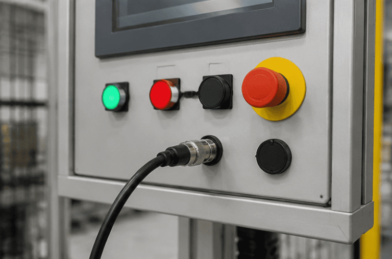
An M12 male connector 5-pin B-coded may look like a straightforward line item, but its name does not…
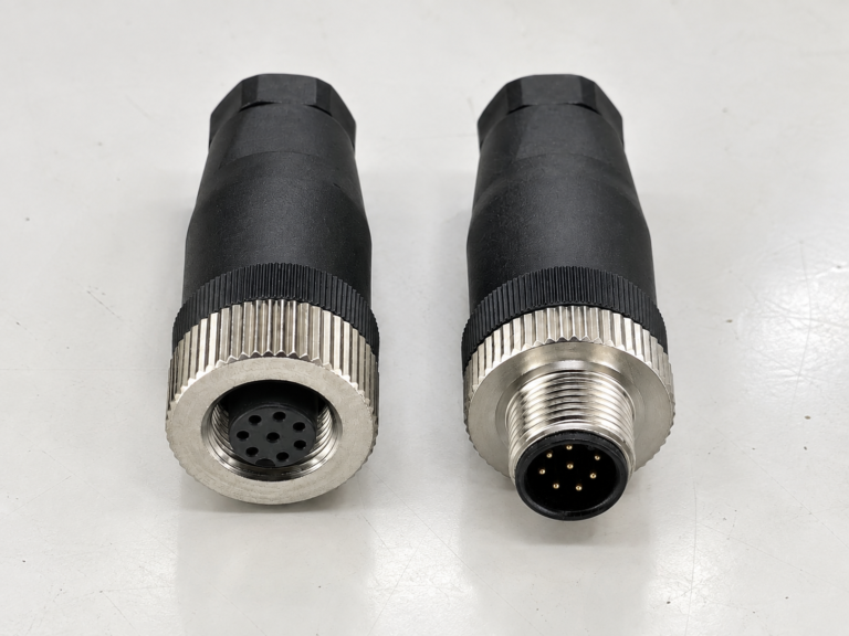
M12 connectors can carry different voltage ratings, so a buyer cannot choose one safely from the connector size…
NITAI manufactures terminal blocks, M8/M12 waterproof connectors and industrial distribution modules for global OEMs, distributors and automation customers.
Leave a Reply