Sep 10, 2026
Top M12 Connector Manufacturers: 10 Global Brands Compared
Choosing an M12 connector manufacturer is not simply a matter of selecting the best-known name. The right supplier…

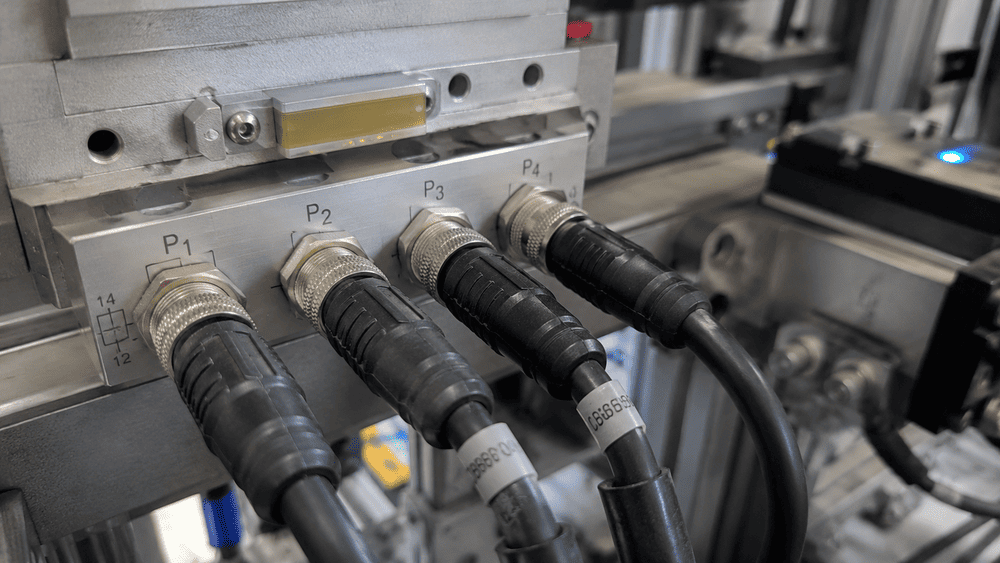
An M12 connector is a compact circular industrial connector with an M12 × 1 screw-locking interface. It is widely used to carry sensor signals, fieldbus communication, industrial Ethernet data, and electrical power between devices in automation systems.
The name M12 identifies the metric locking-thread family. It does not tell you the coding, pin count, gender, wiring, electrical rating, or mounting structure. Two connectors can both be called M12 and still be unable to mate or work together.
That distinction matters in real projects. I often receive inquiries in which the M12 thread appears correct, but the coding, pin layout, PCB footprint, rear thread, cable, or wiring definition does not match the equipment. This guide explains how the M12 family works and what we check before recommending a connector or cable assembly.
The M refers to a metric thread, and 12 refers to the nominal thread diameter. Most standard screw-locking M12 interfaces use an M12 × 1 thread, meaning a nominal 12 mm diameter and a 1 mm thread pitch.
This does not mean that the complete connector body is only 12 mm wide. A coupling nut, molded body, cable gland, panel flange, shield housing, or right-angle outlet can make the overall dimensions much larger.
M12 connectors are part of a standardized industrial connector family. IEC 61076-2-101 specifies circular connectors with M12 screw locking for industrial applications, including fixed and free connectors and rewireable and non-rewireable versions.1
In practical terms, the standardized mating interface provides a common starting point, but it is not a complete part number. We still need to identify the connector's coding, contacts, gender, electrical function, and physical structure.
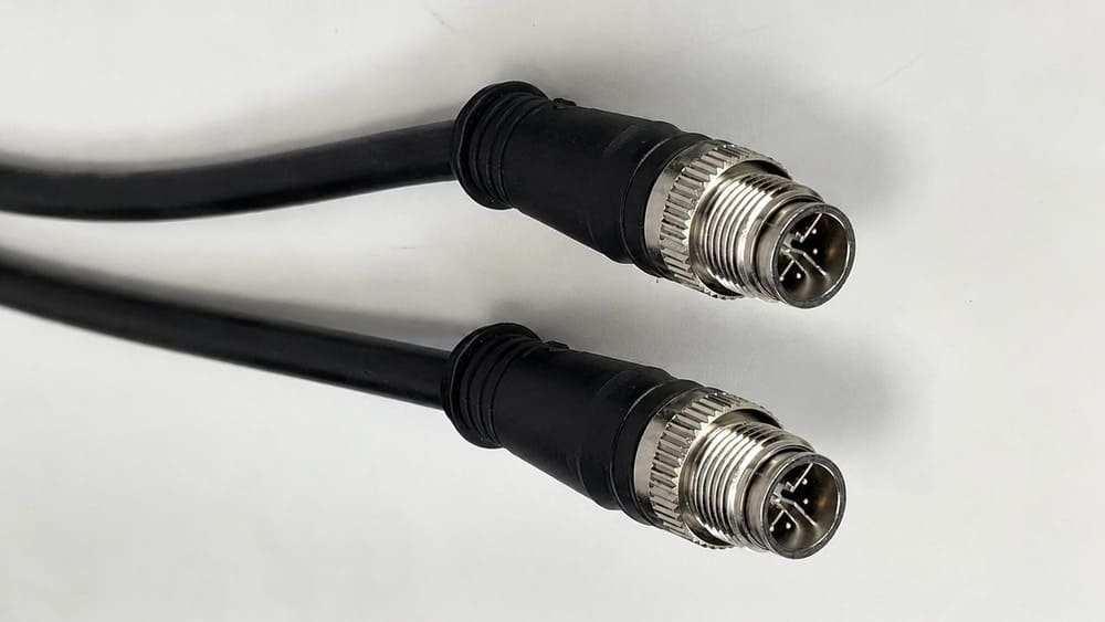
A typical M12 connector has a round mating face, a threaded coupling mechanism, contact pins or sockets, a coding keyway, and a sealing element.
Common visible features include:
The mating face is usually more useful than the side view when identifying a connector. Several products can have nearly identical black molded bodies while using different contact arrangements or coding features.
When a customer sends only one side-view photo, I normally ask for a clear front-face photo, the pin count, male or female contacts, and several measured dimensions. The mating interface may be standardized, while the overall length, rear thread, panel cutout, PCB pins, and mounting height can vary between manufacturers and product series.
For a picture-based identification process, see our visual guide to what an M12 connector looks like.
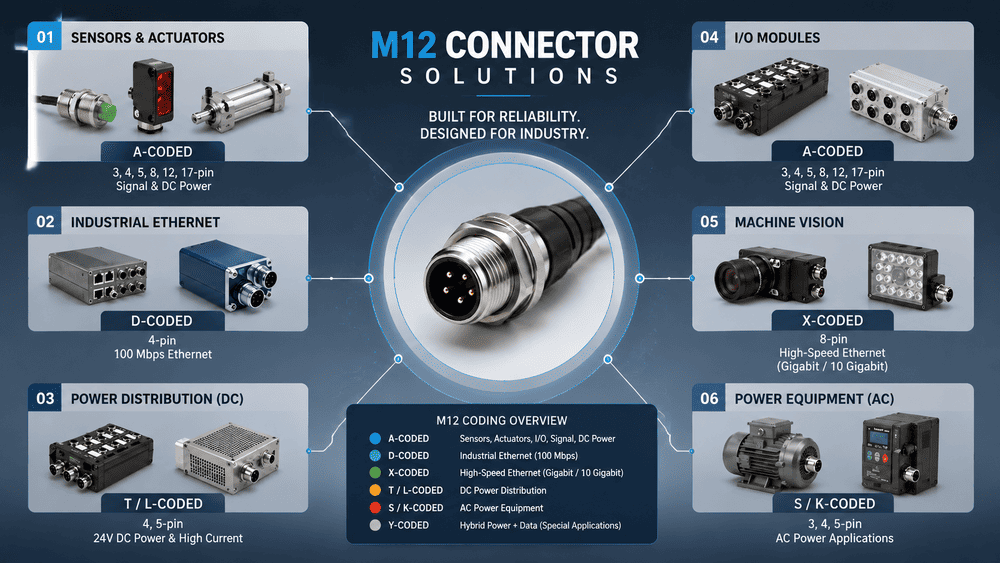
M12 connectors are mainly used for signal, data, and power connections in industrial equipment. Molex describes the M12 family as an industrial connectivity system covering signal, data, and power applications.2
| Function | Common Coding | Typical Equipment | Important Checks |
|---|---|---|---|
| Sensor and actuator signals | A-coded | Proximity sensors, photoelectric sensors, valves, switches, I/O modules | Pin count, device pinout, PNP/NPN, analog or digital signal |
| Fieldbus communication | B-coded | PROFIBUS and legacy fieldbus equipment | Protocol, pin assignment, cable impedance, shielding |
| Industrial Ethernet | D-coded or X-coded | PLCs, switches, cameras, robots, remote I/O | Required speed, cable category, pair structure, shielding |
| AC power | S-, K-, or other application-specific power coding | Motors, drives, and machine equipment | Voltage, current, conductor size, protective earth |
| DC power | T- or L-coded | Distributed I/O, field devices, compact motors, power distribution | Voltage, current, contact arrangement, wire gauge |
These are common associations, not permission to select by application name alone. The device datasheet and the selected connector drawing remain the final references.
A-coded M12 connectors are widely used with industrial sensors, actuators, switches, solenoid devices, and standard I/O.
For a sensor project, I normally confirm:
IO-Link is a familiar example. The IO-Link system description shows a typical M12 connection with pin 1 for 24 V, pin 3 for 0 V, and pin 4 for the C/Q switching and communication line.3 However, the remaining contacts and device behavior can differ, so we still check the device documentation.
D-coded and X-coded connectors are the two M12 types most often associated with industrial Ethernet.
Binder describes D-coded M12 connectors as industrial Ethernet products that reach Cat 5 performance and are available for applications such as PROFINET and Ethernet.4 TE Connectivity describes X-coded M12 products for Cat 6A Ethernet with data rates up to 10 Gbit/s.5
The connector alone does not set the data rate. A stable Ethernet cable assembly also depends on:
I have seen customers request X-coded connectors simply because 10 Gbit/s sounds safer for the future. If their equipment supports only 100 Mbit/s and the installed network is already D-coded, a D-coded assembly can be the more economical and compatible choice. If the project involves high-resolution machine vision or high-volume data acquisition, X-coded with the correct Cat 6A cable and shielding becomes much more relevant.
For more detail, read our M12 X-coded connector guide.
M12 power connectors provide compact AC or DC power interfaces for motors, drives, field I/O, and distributed equipment.
Phoenix Contact groups S- and K-coded M12 interfaces with AC applications and T- and L-coded interfaces with DC power applications.6
Power selection requires more than the number of contacts. We check:
| Electrical Detail | Why It Matters |
|---|---|
| AC or DC | Determines the appropriate coding family |
| Rated voltage | Must meet or exceed the circuit requirement within the product specification |
| Rated current | Must match the contacts, conductor size, and temperature conditions |
| Protective earth or functional earth | Must match the device and connector contact arrangement |
| Conductor size | Affects current capacity, voltage drop, and termination fit |
| Cable outside diameter | Must fit the gland, seal, or molded design |
| Temperature and environment | Affect the connector, seal, and cable material |
Never replace one power coding with another merely because both products have an M12 thread. The different keyways and contact arrangements exist to separate incompatible circuits.
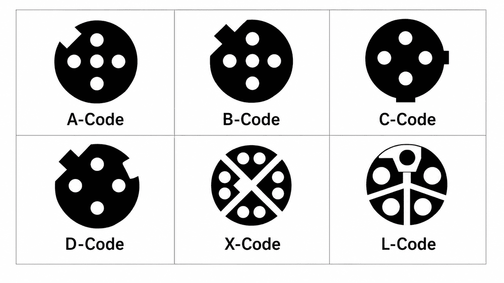
Coding is the mechanical keying system on the mating face. It helps prevent connectors intended for different electrical functions from being plugged into one another.
| M12 Coding | Typical Purpose | Typical Contact Arrangement | Selection Note |
|---|---|---|---|
| A-coded | Sensors, actuators, I/O, general signals, IO-Link | Multiple options, commonly 3, 4, 5, 8, 12, or 17 contacts | Pin count and device wiring must still be confirmed |
| B-coded | PROFIBUS and fieldbus communication | Commonly 5 contacts | Do not confuse with A-coded products of a similar size |
| C-coded | Legacy AC sensor and actuator power | Code-specific power arrangements | Less common in new inquiries; confirm the installed equipment |
| D-coded | 100 Mbit/s industrial Ethernet | 4 contacts, 2 data pairs | Common for PROFINET, EtherNet/IP, and EtherCAT physical links |
| X-coded | High-speed industrial Ethernet | 8 contacts, 4 data pairs | Complete Cat 6A channel design is required for 10 Gbit/s performance |
| S-coded | AC power | Code-specific contacts and PE arrangement | Confirm voltage, current, and grounding |
| T-coded | DC power | Code-specific DC power arrangement | Confirm conductor size and current requirement |
| K-coded | Higher-power AC applications | Code-specific contacts and PE arrangement | Confirm phase and grounding requirements |
| L-coded | Compact DC power distribution | Code-specific contacts and FE/PE arrangement | Confirm the exact device interface and rating |
This table is an application overview, not a substitute for a drawing. Ratings and available contact arrangements vary by connector series.
One of the most common mistakes is to order an “M12 4-pin connector” without specifying the code. A 4-pin A-coded sensor connector and a 4-pin D-coded Ethernet connector are not interchangeable, even though both have four contacts.
Our M12 connector coding guide explains each code in more detail.
An M12 connector does not have one fixed pin count. Depending on the coding and application, the family includes configurations from low-contact power or signal products to high-density 12- and 17-contact signal connectors.
Common pin counts include:
Pin count is only one part of the description. A complete specification normally includes:
M12 + coding + pin count + gender + orientation + mounting or termination + electrical and cable requirements
For example:
M12 A-coded, 4-pin male, straight molded cable, 2 m PVC, unshielded, pin-to-pin wiring
That description is much safer than “M12 4 pin.”
There is no single pinout that applies to every M12 connector. Coding, contact count, male or female mating face, viewing direction, and the connected device all affect how a diagram should be interpreted.
In a common 4-pin A-coded sensor cable, the usual conductor colors are:
| Pin | Common Wire Color | Common Sensor-Cable Role |
|---|---|---|
| 1 | Brown | Positive supply |
| 2 | White | Auxiliary input or output, device-dependent |
| 3 | Blue | 0 V |
| 4 | Black | Main switching or C/Q signal |
This convention is useful, but it does not prove that every device assigns the same electrical function to every contact. Always compare the connector drawing with the equipment wiring diagram.
The viewing direction is another frequent source of errors. Male and female contact faces can appear mirrored, and a wiring-side drawing may not match a mating-face drawing. We label the view direction on drawings whenever possible.
For detailed sensor wiring examples, see our M12 A-coded pinout guide.
An M12 male connector has contact pins. An M12 female connector has contact sockets.
Identify gender from the electrical contacts, not only from the metal thread or coupling nut. Depending on the product design, a female insert may sit inside an externally threaded panel housing, and a male insert may be surrounded by a rotating coupling nut.
Before we quote a product, we confirm both sides of the connection:
This avoids a common situation in which the shell appears correct but the customer receives the opposite contact gender.
M12 is available in several physical and termination styles.
| Structure | Best Used When | Details to Confirm |
|---|---|---|
| Molded cable assembly | A ready-to-install sealed cable is required | Length, cable type, wiring, shielding, straight or angled outlet |
| Field-wireable connector | Cable length must be assembled or repaired on site | Cable diameter, conductor size, termination method, sealing procedure |
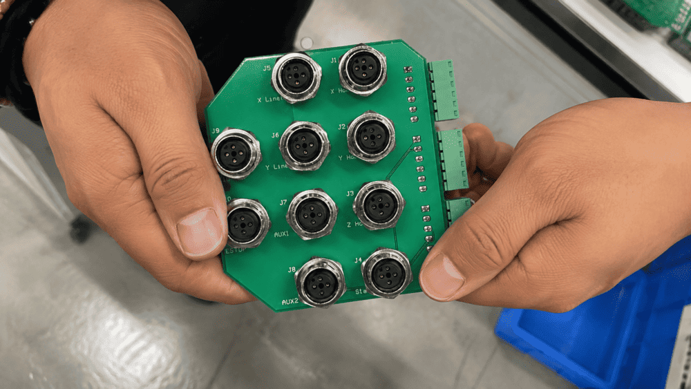
| Panel-mount receptacle | A fixed port is needed on an enclosure or machine | Front or rear mount, cutout, panel thickness, thread length, gasket |
| PCB-mount connector | The interface connects directly to a circuit board | PCB footprint, pin spacing, orientation, height, mounting holes |
| Adapter cable | Two different interfaces must be connected | M12 code, opposite connector, wiring map, Ethernet category if applicable |
We normally recommend a molded assembly when the customer wants controlled wiring, strain relief, and repeatable sealing from a finished cable.
The main decisions are:
Field-wireable connectors are useful for installation, repair, and custom cable lengths on site. Terminations may use screw, spring, IDC, solder, or crimp technology.
Their environmental performance depends heavily on assembly. The cable gland must match the cable diameter, the jacket must be seated correctly, the shield must be terminated as designed, and the housing must be tightened to the specified torque.
Panel and PCB products require dimensional confirmation. I ask customers for the panel cutout or PCB layout because the M12 mating face can be standard while the rear structure is not.
We compare:
In one sample project, a customer expected a standard multi-pin connector to match a PCB footprint whose lower holes were arranged differently. The contact layout of the standard connector could not simply be moved without creating a nonstandard mating product. The practical solution was to correct the PCB footprint or select a connector designed for that footprint. That is why drawing confirmation should happen before tooling, PCB production, or volume ordering.
An M12 connector is not automatically waterproof merely because it belongs to the M12 family. Many products are designed for IP67 or IP68 protection, but the rating applies only under the stated test and installation conditions.
IEC 60529 defines the IP Code used to classify protection provided by enclosures against access, solid foreign objects, dust, and water.7
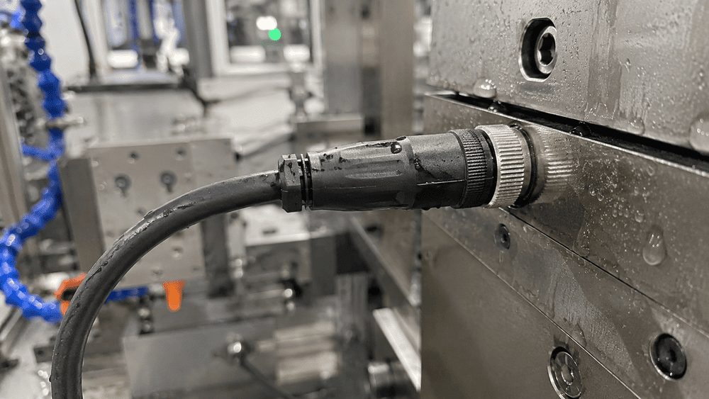
The final protection of an M12 connection depends on the complete system:
PVC and PUR cable assemblies can both be designed to meet IP67. PUR does not automatically mean IP68, and PVC does not automatically mean poor water protection. The jacket material affects flexibility, abrasion resistance, oil resistance, and cost; the complete connector and sealing design determine the assembly's ingress protection.
The economical choice depends on movement and environment, not on a belief that the more expensive material is always better.
| Application Condition | Usual Starting Choice | Why |
|---|---|---|
| Fixed equipment, normal indoor environment | PVC | Economical and suitable for many static installations |
| Occasional maintenance movement | PVC or application-specific cable | Depends on bend radius and handling frequency |
| Repeated flexing or drag-chain movement | Dynamic-rated PUR cable | Better suited to abrasion and repeated motion when the cable construction is rated for it |
| Oil, coolant, or mechanical wear | PUR or another resistant compound | Material must match the specific chemical and mechanical exposure |
| Outdoor or special-temperature use | Application-specific cable | UV, temperature, water, and certification requirements must be checked |
In our quotations, we do not automatically recommend PUR. If the equipment is fixed, the environment is ordinary, and there is no repeated dragging or bending, PVC often provides the better cost-to-performance balance.
If the customer specifies frequent bending, cable-chain use, repeated swinging, oil exposure, or high abrasion, we are more likely to recommend a suitable PUR construction. It costs more, but the additional mechanical performance is relevant in those conditions.
Read our full PUR vs PVC cable selection guide before choosing a jacket.
Use the following order instead of starting with price or pin count:
The right connector is not necessarily the highest-specification or lowest-price option. It is the option that meets the equipment, environment, expected service life, and budget without unnecessary cost.
Most customers already have part of the specification. They may send a device model, old connector, PCB drawing, dimensional drawing, part number, or sample photo.
Our usual process is:
After sample testing, the requested changes are often small but important: cable color, cable length, wire colors, tail treatment, connector height, outlet direction, labeling, or packaging. If the sample fits and performs correctly, the confirmed design can move directly into volume production.
This is why I prefer to review the application and drawing before offering the most expensive material or a supposedly “universal” M12 connector. Matching the real operating conditions usually produces a more reliable and economical result.
| Information | Example |
|---|---|
| Application | Sensor, Ethernet camera, motor, or control cabinet |
| Coding | A, B, D, X, S, T, K, or L |
| Contact count | 3-pin, 4-pin, 5-pin, or 8-pin |
| Gender | Male pins or female sockets |
| Product structure | Molded cable, field-wireable, panel-mount, or PCB-mount |
| Orientation | Straight or right angle |
| Electrical requirement | Signal type, network speed, voltage, and current |
| Protection requirement | IP67, IP68, or project-specific conditions |
| Cable requirement | Length, PVC/PUR, wire gauge, color, and shielding |
| Reference information | Device model, drawing, photo, old part number, or sample |
If you do not have every detail, start with the device model, application, mating-face photo, and any available drawing. We can use those to identify the missing questions.
It is both a metric interface size and the name of a broad industrial connector family. The M12 × 1 mating thread does not define the coding, contact count, gender, pinout, or electrical function.
A-coded M12 connectors are among the most common for sensors, actuators, and general industrial signals. However, the most suitable product depends on the equipment interface and application. See our guide to the most common M12 connector configurations.
Common configurations include 2, 3, 4, 5, 6, 8, 12, and 17 contacts. Not every pin count is available for every coding. Pin count alone is not a complete product specification.
No. Coding, keyway, contact count, gender, contact layout, electrical rating, and device pinout must match. Two products with the same M12 thread may be intentionally prevented from mating.
No. Many are available with IP67 or IP68 ratings, but protection depends on the exact product and stated conditions, including proper mating, seals, cable entry, panel gasket, assembly, and protective caps for unused ports.
D-coded connectors are commonly used for 100 Mbit/s industrial Ethernet. X-coded connectors use four data pairs and can support up to 10 Gbit/s when the complete Cat 6A channel and equipment support that speed.
Yes. M12 includes dedicated power codings for AC and DC applications. The correct code must be selected according to voltage, current, conductor size, grounding, and the device interface.
A clear mating-face photo can help identify gender, pin count, and likely coding, but a final match may still require dimensions, a device model, a drawing, or an old part number. Side-view photos alone are often insufficient.
An M12 connector is a standardized circular industrial interface used for signal, data, and power connections. Its M12 × 1 locking system is compact and secure, but “M12” is only the beginning of the specification.
To select the correct product, confirm:
Binder's M12 overview likewise presents the family as a broad range of coded signal, data, power, cable, panel, and field-wireable solutions rather than one universal connector.8
NITAI supplies M12 connectors and cable assemblies, including M12 4-pin connectors and M12 5-pin connectors.
If you have a device model, drawing, PCB layout, old sample, or wiring requirement, send it to us for product matching and quotation.
[IEC 61076-2-101:2024](https://webstore.iec.ch/en/publication/77773), International Electrotechnical Commission. This standard covers M12 screw-locking circular connector detail specifications for industrial applications. Exact interfaces and ratings depend on the applicable standard sheet and product design. ↩
[M12 Connectors](https://www.molex.com/en-us/products/connectors/industrial-connectors/m12-connectors), Molex. This product-family overview supports the use of M12 connectivity for industrial signal, data, and power applications. ↩
[IO-Link System Description](https://io-link.com/fileadmin/user_upload/Downloads/About_IO-Link/IO-Link_System_Description_eng_2018.pdf), IO-Link Community. This document explains typical IO-Link M12 port wiring, including the L+, L−, and C/Q contacts. Device-specific assignments must still be checked. ↩
[M12 D-Coded Connectors](https://www.binder-connector.com/en/products/automation-technology-speciality-connectors/m12-d), binder. This product-family page supports D-coded M12 use for Cat 5 industrial Ethernet and PROFINET applications. ↩
[Industrial M12 X-Code Connectors](https://www.te.com/en/products/connectors/circular-connectors/intersection/m8m12/m12-x-code.html), TE Connectivity. This page supports Cat 6A industrial Ethernet and data rates up to 10 Gbit/s for appropriate X-coded products and complete channels. ↩
[M12 Power](https://www.phoenixcontact.com/en-us/us-lp-m12power), Phoenix Contact. This overview groups M12 power codings for compact AC and DC distribution. Final electrical ratings must be taken from the selected product datasheet. ↩
[Ingress Protection Ratings](https://www.iec.ch/ip-ratings), International Electrotechnical Commission. This page explains the IP classification system associated with IEC 60529. An IP rating applies under defined test and installation conditions. ↩
[M12 Connectors: Types, Coding, Pins, and Cables](https://www.binder-connector.com/en/news/m12-connectors-complete-guide-to-our-most-prominent-series), binder. This overview supports the description of M12 as a multi-code connector family with cable, panel, field-wireable, signal, data, and power variants. ↩
Choosing an M12 connector manufacturer is not simply a matter of selecting the best-known name. The right supplier…
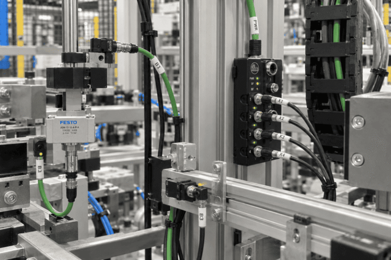
An M8 connector is used when industrial equipment needs reliable signal, power, or data connections in a compact…
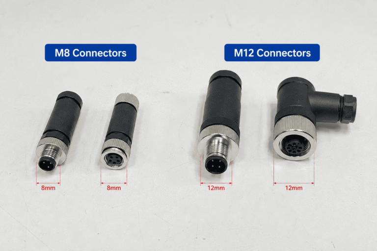
M8 and M12 connectors both appear throughout industrial automation, but they are not interchangeable drop-in options. Choose M8…
NITAI manufactures terminal blocks, M8/M12 waterproof connectors and industrial distribution modules for global OEMs, distributors and automation customers.
Leave a Reply