Sep 10, 2026
Top M12 Connector Manufacturers: 10 Global Brands Compared
Choosing an M12 connector manufacturer is not simply a matter of selecting the best-known name. The right supplier…

Most engineers and industrial buyers asking this question are not looking for a basic definition of M12 coding.
They are usually trying to determine which M12 configuration is most likely to match a sensor, remote I/O module, machine panel, control cabinet, or replacement cable—and whether the supplier understands the details that decide compatibility.
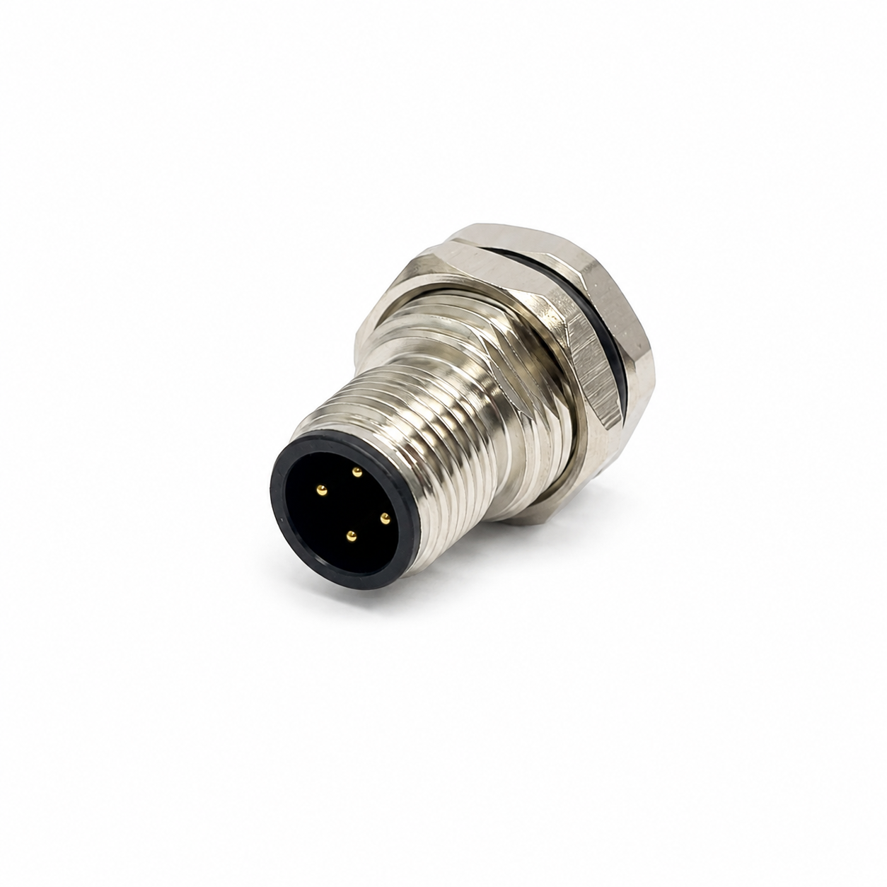
For general industrial automation, the most common M12 connector is typically the A-coded M12 connector. We see it most often in sensor cables, actuator connections, digital I/O, standard control signals, panel-mount interfaces, and general machine wiring.
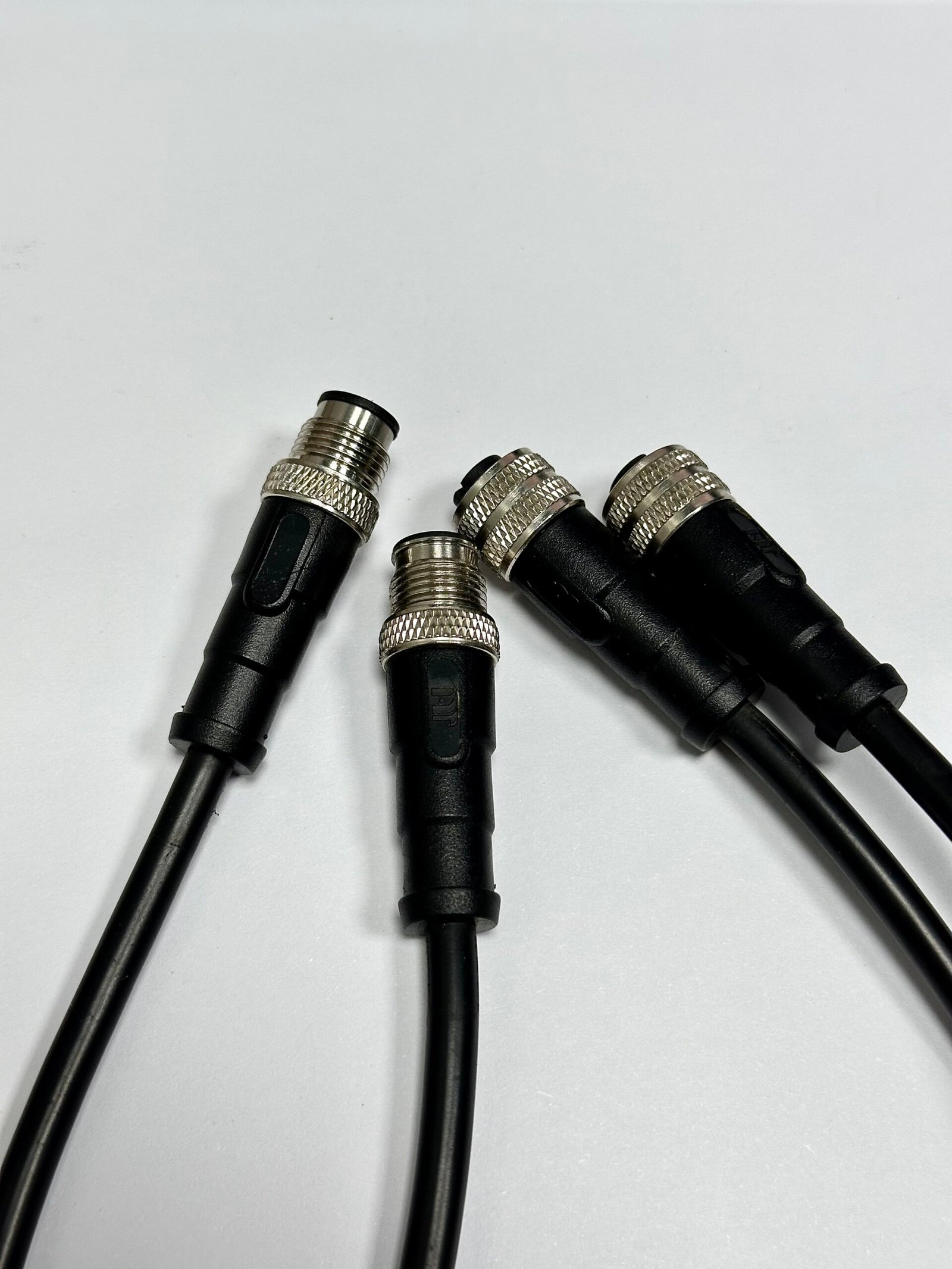
Common M12 cable assemblies used for industrial automation and equipment connections.
From the M12 inquiries we receive at NITAI, A-coded products appear more frequently than other coding types.
However, customers rarely need only “an A-coded connector.”
They normally need a specific combination of:
This is where an experienced connector manufacturer should add value.
Our job is not simply to identify A-coded as the most common option. It is to confirm whether the exact A-coded configuration will mate with the equipment, fit the available installation space, and follow the required wiring before production begins.
A customer may already know that A-coded is common but still need help deciding whether it suits the actual equipment.
We see more A-coded projects because sensors, actuators, I/O modules, switches, and ordinary control connections appear throughout industrial automation, while Ethernet, fieldbus, and higher-power applications represent more specialized requirements.
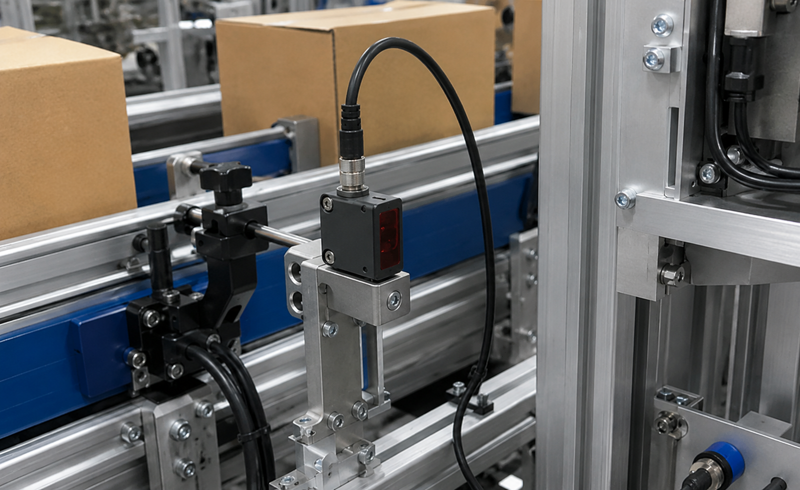
A typical M12 field connection used between industrial equipment and automation devices.
The current IEC 61076-2-101:2024 standard defines M12 screw-locking connector interfaces with 2 to 17 contacts1. The actual signal, data, voltage, current, and mating requirements still depend on the coding and product configuration.
In practical automation projects, A-coded M12 connectors are frequently associated with:
The IO-Link system description shows how M12 interfaces are used for sensors, actuators, and master ports2. It describes common 4-pin connections for sensors and 5-pin connections for actuators and master ports.
That is consistent with what we see in customer inquiries: many projects are built around ordinary field signals rather than high-speed industrial Ethernet or dedicated power transmission.
We do not use “most common” as a claim about global sales percentages.
It is an observation based on the RFQs, drawings, connector photos, and cable requirements sent to us.
The requests we see most often include:
These projects are common because A-coded products can cover a wide range of standard signal applications while still offering many mechanical and wiring configurations.
An inquiry may look simple at first but still leave several important questions unanswered.
When a customer asks for an A-coded M12 connector, the actual requirement is normally a complete interface and wiring configuration—not just the coding name.
For example, we may receive an inquiry that says:
We need an M12 5-pin female cable, 3 meters.
That information is not yet enough to confirm the correct product.
Before quoting, we still need to determine:
| Detail to Confirm | Why It Matters |
|---|---|
| A-coded or another coding | Different keyways are not interchangeable |
| Female mating face | Gender descriptions can be misunderstood |
| Straight or right-angle | Installation space may limit cable direction |
| 3-meter PVC or PUR cable | Cable material depends on movement and environment |
| Shielded or unshielded | Required for some signals or equipment designs |
| Open-wire or second connector | Determines the complete cable structure |
| Pin-to-wire assignment | The same 5-pin interface may use different wiring |
| Static or moving installation | Cable construction must suit the application |
| Required quantity | Affects sample and production planning |
A supplier who immediately quotes only from “M12 5-pin female” may provide a product that looks correct but does not match the equipment.
Our normal approach is to convert the customer’s short description into a complete technical specification before confirming the model.
Some customers have a complete drawing. Others send only an old cable, an equipment photo, or a product model.
We start with whatever information the customer has, then identify the missing details that could affect mating, wiring, installation, or production.
| What the Customer Sends | What We Check |
|---|---|
| Connector front-view photo | Coding key, pin count, gender, and mating interface |
| Old cable sample | Connector structure, cable, length, wiring, and second end |
| Equipment model | Required interface, electrical function, and available documentation |
| Panel drawing | Mounting direction, thread, dimensions, and available rear space |
| Pinout diagram | Pin numbering, view direction, wire colors, and function |
| Cable specification | Jacket, conductor size, shielding, flexing, and environment |
| Application description | Sensor, I/O, Ethernet, power, static, or moving use |
| Existing supplier model | Possible equivalent structure and dimensions |
One common source of cable errors is the drawing direction.
The same connector may appear different when viewed from:
The apparent pin positions can be mirrored.
When we review a customer drawing, we therefore check whether it represents the mating side or wiring side before confirming the pin-to-pin definition.
A technically correct pinout shown from the wrong viewing direction can still result in a cable that does not work on the machine.
The number of contacts does not fully define an M12 connector.
For example:
This is why we ask for the equipment pinout whenever the cable is customized.
A-coded projects usually fall into several practical categories.
A common request is an A-coded M12 connector on one end and stripped or prepared wires on the other.
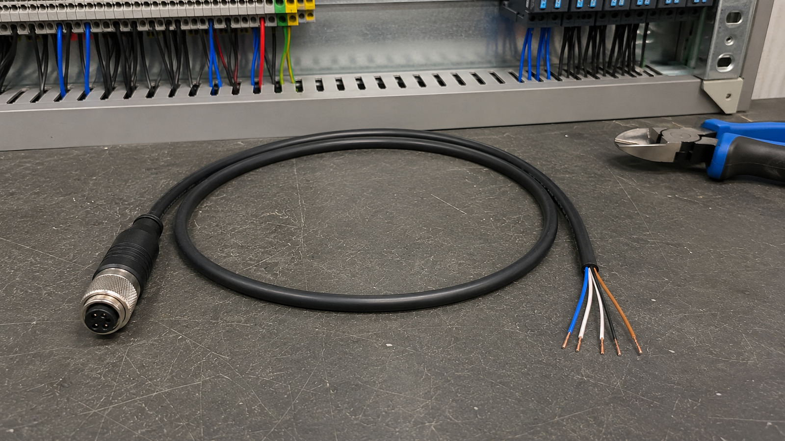
An M12 cable assembly with an open-wire tail for connection inside a machine or control cabinet.
The initial request may include:
Before production, we normally confirm:
This type of cable may appear simple, but a wrong wire color, pin assignment, or tail treatment can create additional work during machine assembly.
Another frequent project is an M12 extension cable between a sensor, actuator, distribution box, or machine interface.
The customer may require:
For this type of project, we check whether the cable is:
A cable can have the correct connectors on both ends and still be unsuitable if its jacket, flexibility, outer diameter, or connector direction does not match the machine.
A customer may request an A-coded panel socket for a controller, control cabinet, sensor housing, or industrial machine.
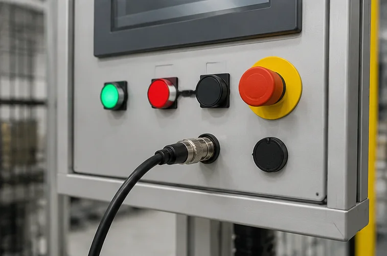
A panel-mount M12 interface connects the external field cable to the wiring inside the equipment.
Before recommending a panel connector, we normally review:
The words “M12 panel socket” do not define all these details.
A front-mounted and rear-mounted product may have a similar mating face but a different body, thread position, sealing arrangement, and installation method.
Replacement projects often begin with an old cable photo or an existing supplier model.
The customer may not have the original drawing.
In this situation, we compare:
We do not assume that a visually similar cable is electrically identical.
When the original wiring cannot be confirmed, we recommend verifying the pinout or testing a sample before approving volume production.
A buyer may understand the interface but still need to know whether the supplier can manufacture the required structure.
For A-coded M12 projects, we can review cable connectors, molded cable assemblies, field-wireable connectors, panel-mount sockets, PCB versions, and customer-specific cable configurations according to the model and technical requirements.
Typical options include:
| Category | Available Project Options |
|---|---|
| Pin count | 2, 3, 4, 5, 6, 8, 12, or 17 contacts, depending on product |
| Gender | Male or female |
| Orientation | Straight or right-angle |
| Cable product | Single-ended, double-ended, or extension cable |
| Cable end | Open wire, second connector, terminal, or customer-defined treatment |
| Mounting | Cable, front panel, rear panel, PCB, or flange structure |
| Termination | Solder, screw, PCB, molded cable, or model-specific termination |
| Cable jacket | PVC, PUR, or project-specific cable |
| Shielding | Shielded or unshielded, depending on configuration |
| Cable length | Standard or customized |
| Wiring | Standard or customer-defined pin-to-pin connection |
| Appearance | Product labeling and packaging can be reviewed for OEM projects |
Not every combination belongs to one standard model.
For example, the available termination method may change according to the connector body, pin count, cable diameter, shielding structure, and mounting method.
This is why we prefer to review the complete project instead of confirming capability from one short product name.
For a custom molded cable, the most useful information is:
A simple cable definition may look like this:
| Item | Requirement |
|---|---|
| End A | M12 A-coded female, straight, 5-pin |
| End B | Open wire |
| Cable | Black PUR, 5-core |
| Length | 3 meters |
| Wiring | Pin 1–brown, 2–white, 3–blue, 4–black, 5–gray |
| Tail | 50 mm stripped, ferrules fitted |
| Application | Sensor connection on automated machinery |
This gives us enough information to review the connector, cable, wiring, and tail treatment together.
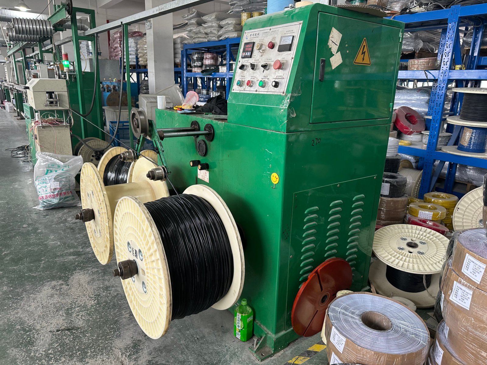
M12 connector production and assembly work at NITAI.
A-coded identifies an important part of the interface, but it does not confirm the entire product.
Two A-coded connectors can still fail to mate, fit, or work correctly because of differences in pin count, gender, wiring, body structure, mounting dimensions, or electrical rating.
The most common risks we check include:
A 4-pin cable cannot replace a 5-pin interface simply because both are A-coded.
The contact pattern and required electrical functions are different.
A customer may describe the cable as a plug while the drawing defines the interface by contact gender.
We confirm the actual male or female contact arrangement rather than relying only on the words “plug” and “socket.”
Two mechanically compatible cables can use different wire assignments.
This is especially important for:
A panel connector may have:
A standard PVC cable may be suitable for fixed indoor wiring but unsuitable for an application requiring repeated movement, abrasion resistance, or oil resistance.
The connector and cable must be selected as one assembly.
Many M12 connectors are designed for industrial ingress protection, but the actual rating depends on the product design, assembly, sealing, and proper mating condition.
We therefore confirm the rating from the selected model rather than assuming every M12 connector automatically provides the same protection level.
A-coded is common, but it should not be selected simply because it is familiar or readily available.
When the connection is designed for a specific fieldbus, industrial Ethernet, or higher-power supply, another M12 coding may be more appropriate.
| Application Requirement | Typical Coding Direction |
|---|---|
| General sensor and control signals | A-coded |
| PROFIBUS or certain fieldbus systems | B-coded |
| 100 Mbps industrial Ethernet | D-coded |
| Higher-speed industrial Ethernet | X-coded |
| AC power connection | S-, K-, or M-coded |
| Low-voltage DC power | T- or L-coded |
For example, Phoenix Contact specifies B-coded M12 interfaces for PROFIBUS applications3.
For Ethernet, D-coded M12 is commonly used as a 100 Mbps industrial Ethernet interface4, while X-coded M12 supports higher-speed data transmission up to 10 Gb/s5.
For power projects, S-, K-, and M-codings are intended for AC applications, while T- and L-codings are used for low-voltage DC applications6.
We keep this comparison short because the purpose is not to teach every coding in one article.
The practical rule is:
Choose the coding from the electrical function and equipment interface—not from popularity alone.
A product photo may be enough to start a discussion, but it is not always enough to approve mass production.
For custom or equipment-matching projects, we prefer to confirm the interface, drawing, pinout, and sample before volume production.
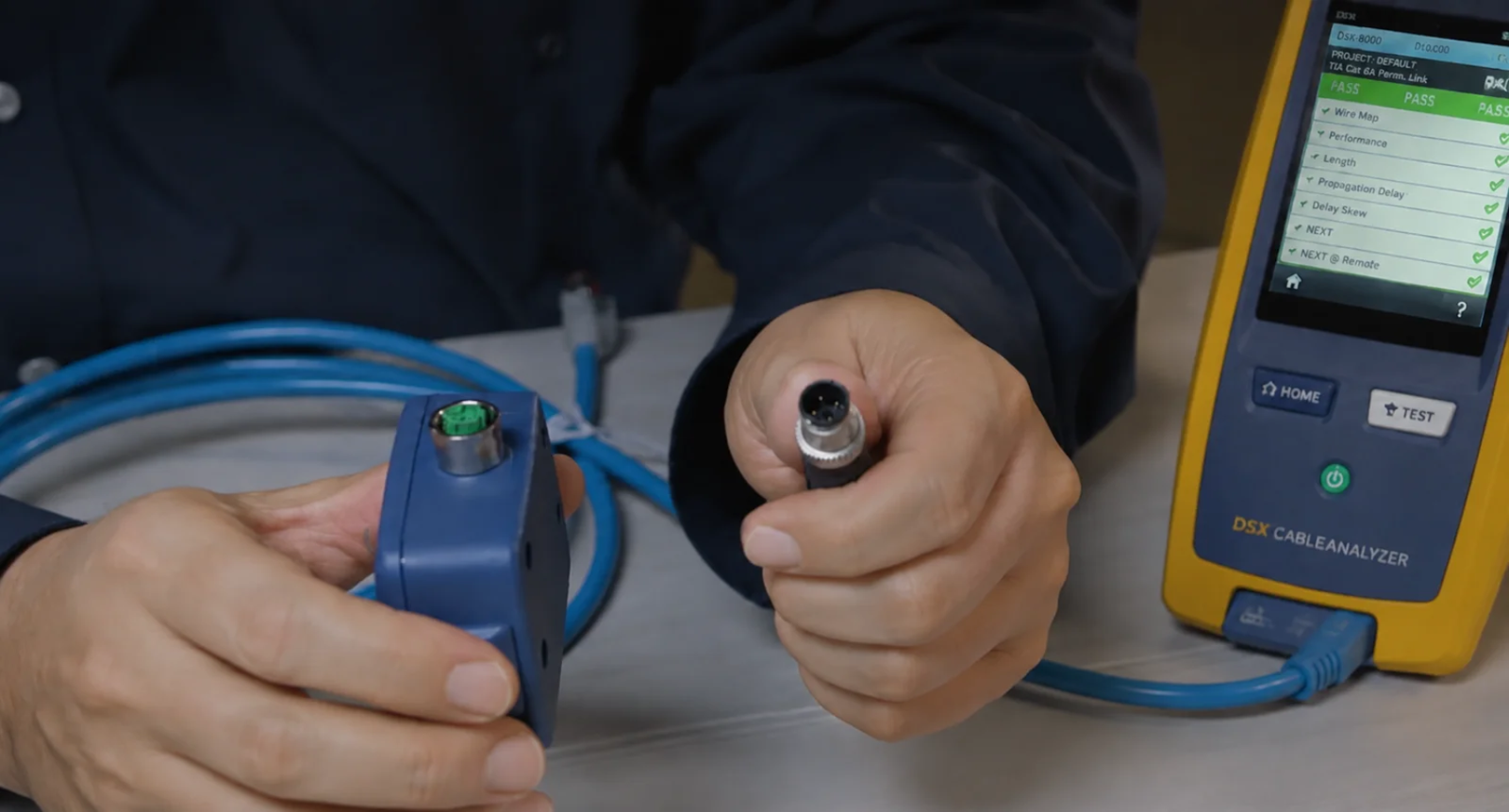
Electrical and wiring checks help confirm the cable before volume production.
Our normal review process is:
The exact inspection plan depends on the project, but typical checks may include:
For equipment replacement projects, the customer’s machine test is especially important because it confirms the cable in the real application.
A drawing creates one agreed reference for both sides.
It can define:
Without this reference, different people may interpret the same email description differently.
The drawing does not replace testing, but it reduces avoidable misunderstandings before the sample is made.
A long technical specification is helpful, but it is not required for the first contact.
The fastest starting point is usually a clear connector photo, the equipment model or drawing, and a description of the required cable or mounting structure.
You can send:
You can copy this format when sending an inquiry:
Application:
Sensor connection for industrial machineryConnector:
M12 A-coded, 5-pin, female, straightSecond End:
Open wireCable:
Black PUR, unshielded, 3 metersWiring:
Please follow the attached pinoutTail Treatment:
50 mm stripped with ferrulesQuantity:
5 samples, followed by an estimated production orderAttachments:
Equipment photo, mating connector photo, and wiring drawing
Even when some details are missing, this gives us a clear starting point for the technical review.
For general industrial automation, A-coded is typically the most common M12 coding. It is widely used for sensors, actuators, standard I/O, and ordinary machine-control signals.
However, the correct coding still depends on the actual equipment interface and electrical function.
The 4-pin A-coded configuration is one of the versions we see most frequently in sensor and standard I/O projects.
A current industrial example is a 4-position A-coded M12 sensor and actuator cable7.
The correct pin count must still follow the equipment specification.
You can also review our M12 4-pin connector options.
A 5-pin version may be used when the equipment requires an additional signal, output, functional connection, or customer-specific contact.
Phoenix Contact also provides a 5-position A-coded M12 sensor and actuator cable8.
Two 5-pin products may still have different wiring, so the pinout must be confirmed.
You can review our M12 5-pin connector options.
A clear mating-face photo can often help us identify the likely coding, pin count, and gender.
However, a photo may not show the internal wiring, electrical rating, rear termination, or exact mounting dimensions. For final confirmation, a drawing, equipment model, or old sample may still be required.
We can review an existing cable from its photos, markings, dimensions, connector interfaces, cable specification, and pinout.
When the original wiring is unknown, we recommend confirming it through the equipment documentation or sample testing before volume production.
Yes.
A-coded and 5-pin define the mechanical interface and number of contacts, but they do not guarantee an identical electrical assignment.
The cable should be manufactured according to the equipment pinout.
Shielded A-coded configurations are available for certain products and cable structures.
The requirement should be confirmed together with the cable construction, connector body, grounding method, and equipment interface.
A-coded connectors may carry low-voltage power and signals within the selected product’s rated voltage and current.
They should not automatically replace dedicated power-coded M12 connectors in higher-power applications.
No single protection rating applies to every M12 product.
The degree of protection depends on the selected model, sealing design, correct assembly, cable entry, and properly mated condition. The required rating should be confirmed from the product specification.
Not necessarily.
A connector photo, equipment model, required cable length, and application description are often enough for an initial review.
We may then ask for the missing dimensions or wiring information before confirming the final product.
For general industrial automation, the A-coded M12 connector is typically the most common choice because it covers a wide range of sensor, actuator, I/O, and ordinary control-signal applications.
However, “A-coded” alone does not define the product a customer needs.
A correct M12 solution may still depend on:
From the projects we review at NITAI, customers are rarely looking for a generic connector. They are trying to match a real sensor, machine, control cabinet, I/O module, or existing cable.
That is why we focus on understanding the equipment and confirming the complete specification before production.
Browse our M12 connector product range, or send us your connector photo, equipment drawing, existing sample, or pinout for product-matching support.
[IEC 61076-2-101:2024 — Connectors for Electrical and Electronic Equipment](https://webstore.iec.ch/en/publication/77773). This standard defines M12 screw-locking connector interfaces with 2 to 17 contacts. It supports the description of the standardized M12 interface family. Individual ratings and functions depend on coding and configuration. ↩
[IO-Link System Description](https://io-link.com/fileadmin/user_upload/Downloads/About_IO-Link/IO-Link_System_Description_eng_2018.pdf). This official system description explains the use of M12 connections for sensors, actuators, and IO-Link master ports. Its pin-count examples apply specifically to IO-Link systems and do not define every M12 application. ↩
[Phoenix Contact — SUBCON-PLUS-PROFIB/35/M12](https://www.phoenixcontact.com/en-pc/products/d-sub-bus-connector-subcon-plus-profib-35-m12-2902320). This product source identifies a B-coded M12 interface for PROFIBUS applications. ↩
[Phoenix Contact — High-Flex Ethernet Cordsets](https://www.phoenixcontact.com/en-us/us-lp-us-highflexethernet). This source describes D-coded M12 as an industrial interface for Ethernet speeds up to 100 Mbps. ↩
[TE Connectivity — Industrial M12 X-Code Connector](https://www.te.com/en/products/connectors/circular-connectors/intersection/m8m12/m12-x-code.html). This source states that the M12 X-coded connector supports data transmission up to 10 Gb/s. ↩
[Phoenix Contact — Signal Cables and Power Cables](https://www.phoenixcontact.com/en-ae/products/cables-and-lines/signal-cables-and-power-cables). This source explains the application direction of S-, K-, and M-coding for AC power and T- and L-coding for low-voltage DC power. ↩
[Phoenix Contact — SAC-4P-M12MS/0,3-PUR/M12FR D Sensor/Actuator Cable](https://www.phoenixcontact.com/en-pc/products/sensoractuator-cable-sac-4p-m12ms-03-pur-m12fr-d-1696057). This product example demonstrates a practical 4-position A-coded M12 cable used for sensor and actuator applications. ↩
[Phoenix Contact — SAC-5P-M12MS Sensor/Actuator Cable](https://www.phoenixcontact.com/en-pc/products/sensoractuator-cable-sac-5p-m12ms-1697098). This product example demonstrates the availability and industrial use of a 5-position A-coded M12 cable with a free cable end. ↩
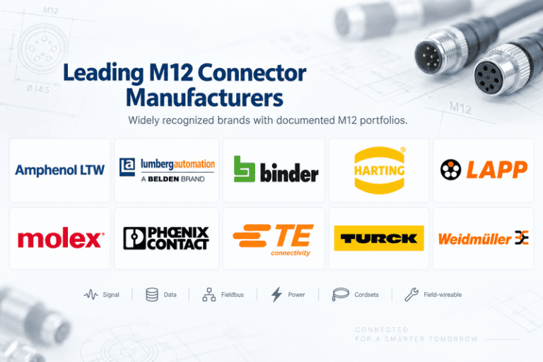
Choosing an M12 connector manufacturer is not simply a matter of selecting the best-known name. The right supplier…
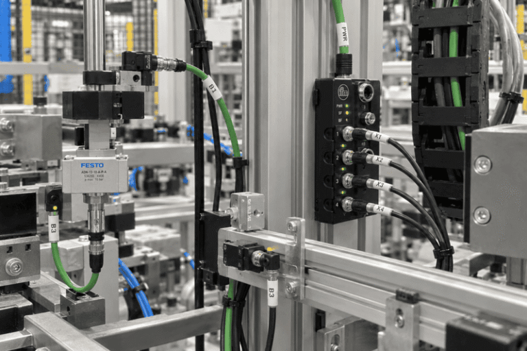
An M8 connector is used when industrial equipment needs reliable signal, power, or data connections in a compact…
A complete 12V power supply box is not simply a 12V power adapter. It normally combines an AC-to-DC…
NITAI manufactures terminal blocks, M8/M12 waterproof connectors and industrial distribution modules for global OEMs, distributors and automation customers.
Leave a Reply