Jun 8, 2026
PVC vs PUR Cable Jackets for M12 Sensor Cables: How to Choose
You’ve picked the right M12 coding and pin count. But the cable jacket material — PVC or PUR…
You know you need an A-coded M12 connector. But which pinout? The wiring for a 3-pin sensor is different from a 4-pin IO-Link device, which is different again from a 5-pin configuration. Get it wrong, and your sensor won’t power up — or worse, you’ll damage the device. Here are the standard pin assignments you’ll encounter in industrial automation.
M12 A-coded connectors follow the pin assignment guidelines in IEC 61076-2-101. Most sensor and actuator manufacturers follow these conventions, but always check the device datasheet. Some manufacturers — especially on proprietary systems — use non-standard pinouts. When in doubt, the device manual overrides everything in this guide.
3-pin is the standard for basic switching sensors: inductive proximity switches, magnetic reed switches, and simple photoelectric sensors that only need to output one signal.
| Pin | Signal | Typical Wire Color |
|---|---|---|
| 1 | +24V DC (supply voltage) | Brown |
| 3 | 0V (ground) | Blue |
| 4 | Switching output (NO or NC) | Black |
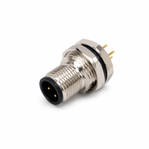
Notice that pin 2 is skipped. This is intentional — the 3-pin layout uses pins 1, 3, and 4 to maintain physical spacing and compatibility with 4-pin sockets. If you look at the face of a male 3-pin M12 connector, the pins form a triangular pattern, not a straight line.
Wire gauge for 3-pin A-coded cables is typically 22 AWG to 18 AWG. The current draw from a simple switching sensor is low, so the cable doesn’t need to be heavy.
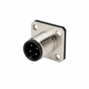
4-pin A-coded is what you’ll see on the majority of industrial sensors. It adds a second output or input, giving the sensor more capability without requiring a larger connector.
| Pin | Signal | Typical Wire Color |
|---|---|---|
| 1 | +24V DC (supply voltage) | Brown |
| 2 | Second output / input / not connected | White |
| 3 | 0V (ground) | Blue |
| 4 | Primary switching output (NO or NC) | Black |
In a standard 4-pin PNP NO (normally open) sensor, pin 4 is the switching output. When the sensor detects its target, pin 4 goes high (+24V). If the sensor has a second output — for example, a photoelectric sensor with both light-on and dark-on outputs — that second output goes to pin 2.
Some manufacturers use pin 2 as an external input instead of an output. For example, a laser distance sensor might accept a teach-in signal on pin 2. Again, the device datasheet is the final authority.
5-pin A-coded is the standard for IO-Link devices and sensors that combine multiple functions — for instance, a sensor that outputs both an analog value and a switching signal through one connector.
| Pin | Signal | Typical Wire Color |
|---|---|---|
| 1 | +24V DC (supply voltage) | Brown |
| 2 | Second output / analog output / IO-Link auxiliary | White |
| 3 | 0V (ground) | Blue |
| 4 | Primary switching output / IO-Link communication (C/Q) | Black |
| 5 | Functional earth (FE) / analog ground / third output | Grey |
In IO-Link mode, pin 4 becomes the C/Q line — bidirectional communication between the sensor and the IO-Link master. Pin 2 is often unused or used as an additional digital input. Pin 5 can serve as functional earth or as a third output, depending on the sensor design.
If you’re converting an older 4-pin sensor installation to IO-Link, the cable is physically compatible — both use the same M12 A-coded interface. But the IO-Link master needs the 5-pin connection to access the full functionality. A 4-pin cable in a 5-pin IO-Link system may still work for basic switching, but you’ll lose the IO-Link communication channel.
| Pin | 3-Pin | 4-Pin | 5-Pin |
|---|---|---|---|
| 1 | +24V (Brown) | +24V (Brown) | +24V (Brown) |
| 2 | — | 2nd output / input (White) | 2nd output / analog (White) |
| 3 | 0V (Blue) | 0V (Blue) | 0V (Blue) |
| 4 | Output (Black) | Output (Black) | Output / C/Q (Black) |
| 5 | — | — | FE / 3rd output (Grey) |
This table makes it clear: pin 1 (brown, +24V) and pin 3 (blue, 0V) are the same across all three configurations. If you’re troubleshooting a sensor that won’t power on, check those two pins first.
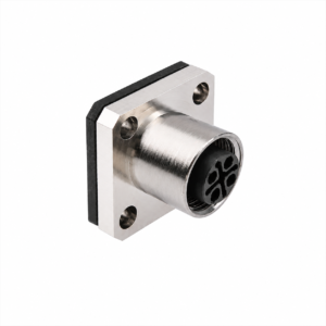
This is a common cause of wiring errors. On a male connector (pins sticking out), pin 1 is at a specific clock position. On a female connector (sockets), pin 1 is at the mirrored position relative to the keyway.
When you’re assembling field-wireable M12 connectors, always refer to the diagram printed on the connector insert or the manufacturer’s datasheet. Don’t assume the pin positions are the same as the mating connector — they’re not.
If you have a sensor with an unknown M12 pinout and no documentation:
If all else fails, contact the sensor manufacturer or the supplier who provided the cable assembly. A photo of the connector face with the pin numbering visible is often enough to get an answer.
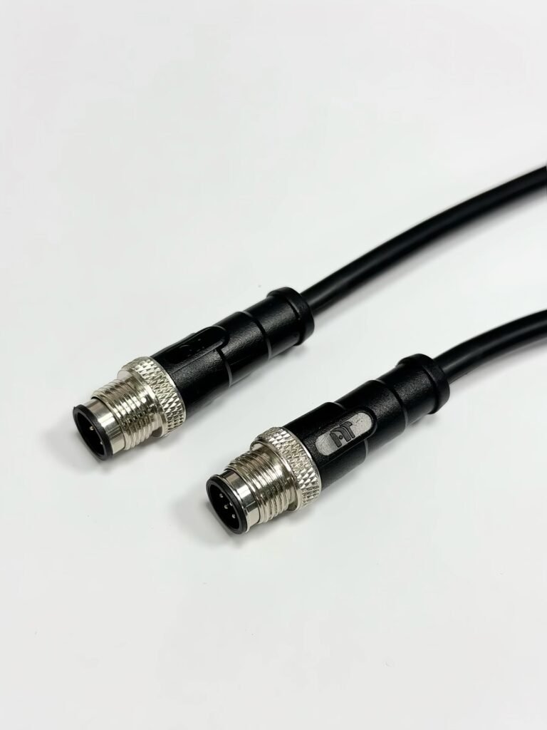
NITAI manufactures M12 A-coded connector cable assemblies in standard 3-pin, 4-pin, and 5-pin configurations. We supply:
If you need a non-standard pinout — for example, a custom wiring for a proprietary sensor interface — we can build to your specification. Send us your pin assignment table or wiring diagram for quotation.
NITAI manufactures terminal blocks, M8/M12 waterproof connectors and industrial distribution modules for global OEMs, distributors and automation customers.
Leave a Reply