Oct 16, 2026
What Is an M12 Male Connector 5-Pin B-Coded?
An M12 male connector 5-pin B-coded may look like a straightforward line item, but its name does not…

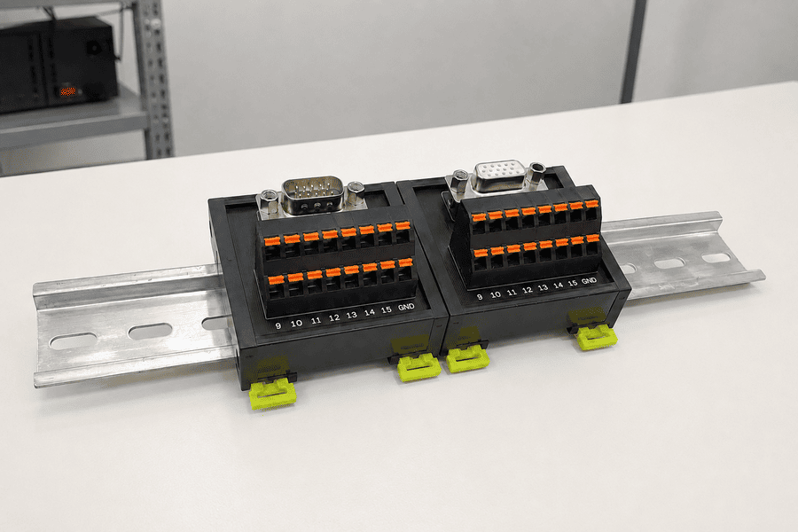
A PLC interface module is typically installed between a PLC I/O card and field wiring to make connections easier to organize, install and maintain. A passive module may only route each signal from a multipole connector to a terminal. Active versions may add relays, fuses, LED indication, electrical isolation or signal conditioning. The number of inputs and outputs alone does not define the module.
Hi, I am Penny from NITAI. I handle overseas product inquiries, selection support, specification clarification and quotations for industrial connectivity products. As we expand our distribution and interface module range, one of the most common opening questions I receive is simply, "How many inputs and outputs does it have?"
That question is useful, but I have learned not to treat it as a complete specification. One supplier may use PLC interface module for a passive connector-to-terminal board, another for a relay interface, and another for hardware that links PLC expansion racks. These products may look related, but they do not perform the same job. I wrote this guide to explain what I check after the first "in/out" question and what information helps us confirm a module correctly.
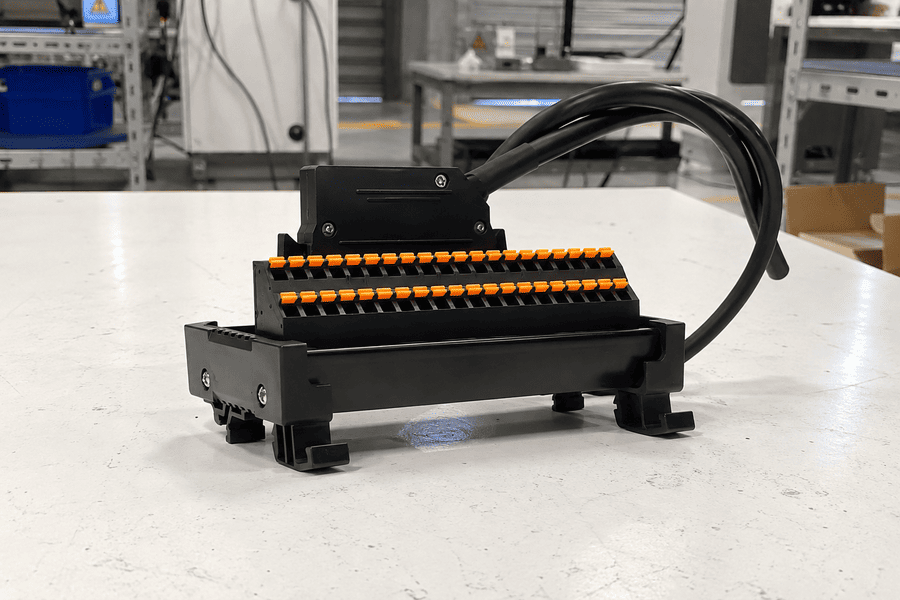
This guide explains the main meanings of PLC interface modules, how passive and active versions differ, what "10-in/10-out" or "16-channel" may mean, and what information is needed before selecting a module.
In control-cabinet wiring, a PLC interface module is a connection device placed between the PLC input/output system and sensors, switches, valves, contactors or other field devices. It usually combines a multipole connector, a printed circuit board and field-side terminal blocks in a DIN-rail-mountable housing.
The module can replace a large group of individually wired terminal blocks. Instead of landing every PLC I/O conductor one by one, the installer connects the PLC card to the interface module through a prewired cable. Field wires are then terminated on clearly identified screw, spring-clamp or push-in terminals.
This is the meaning used by major industrial wiring-system manufacturers. Rockwell Automation describes its Bulletin 1492 system as interface modules and cables connected to digital and analog I/O through prewired cables.1 Weidmuller similarly combines PLC and DCS interface modules with manufacturer-specific preassembled cables.2
A basic PLC interface module does not run the PLC program and does not automatically convert every signal. Its exact function depends on the circuit inside the module.
A typical connection path is:
PLC or Remote I/O Card
        |
PLC Front Connector or Multipole Connector
        |
Prewired Interface Cable
        |
PLC Interface Module
        |
Field Wiring to Sensors, Switches and Actuators
The interface module is normally mounted on a DIN rail inside a control cabinet. It creates a clear boundary between the PLC side and the field-wiring side.
This arrangement can provide several practical benefits:
OMRON describes connector-terminal block conversion units as a way to wire PLC I/O with a single cable, reduce installation work and simplify maintenance.3
These advantages depend on using the correct module, cable and pin assignment. A multipole connector that physically fits is not proof that the electrical mapping is correct.
In the inquiries I currently receive, customers often begin by asking for a module with a certain number of inputs and outputs, such as:
I use this information as the starting point, not the final selection. My next question is whether the circuits are independent, internally commoned or switched through a relay. The words input and output are used differently across product families.
A 10-in/10-out module may contain ten independent circuits. Each incoming terminal or connector pin is routed to one corresponding outgoing terminal.
IN 1  -> OUT 1
IN 2  -> OUT 2
IN 3  -> OUT 3
...
IN 10 -> OUT 10
This is a wiring-conversion or feed-through function. It does not necessarily create ten PLC inputs and ten PLC outputs, and it does not automatically distribute one signal to all terminals.
A 1-in/8-out module may contain one common input bus connected internally to eight output terminals.
          -> OUT 1
          -> OUT 2
IN COMMON -> OUT 3
          -> ...
          -> OUT 8
This is usually a power or common-potential distribution function. It should not be confused with an eight-channel PLC signal interface.
A 16-channel sensor or relay module usually has 16 functional circuits, but it may contain far more than 16 terminals. One sensor channel may require:
One relay channel may require a coil-side input and two or three contact-side terminals. Therefore, channel count and terminal count are not interchangeable.
PLC manufacturers often describe cards by I/O points, such as 16-point or 32-point input modules. The selected interface module and cable must reproduce the correct pin assignment for those points, including common terminals, power connections and unused pins.
The safest rule is simple:
Never select an interface module from the "in/out" number alone. Confirm the internal connection diagram and the meaning of each terminal.
What I ask next: If a customer says "10-in/10-out," I ask whether input 1 connects only to output 1, whether one input is distributed to several outputs, or whether each channel contains another component such as a relay, LED or fuse. This one clarification prevents several very different circuits from being treated as the same product.
The following product families are often grouped under the PLC interface module name.
| Module Type | Main Function | Typical Application | Changes the Signal? |
|---|---|---|---|
| Feed-through interface module | Routes connector pins to field terminals | High-density digital I/O wiring | No |
| Connector-to-terminal conversion module | Converts a multipole connector to screw or spring terminals | PLC cards with 20-, 32-, 37- or 40-pin connectors | No |
| Sensor distribution module | Groups signal, positive supply and common connections | Three-wire sensors and proximity switches | Usually no |
| Power distribution module | Connects one common supply to multiple branches | 24 VDC and 0 V distribution | No |
| Fused interface module | Adds individual or grouped circuit protection | Protected input or output branches | Normally no |
| LED indication module | Displays the status of each circuit | Commissioning and maintenance | Normally no |
| Relay interface module | Uses relays to switch or separate field loads | Solenoids, lamps, contactors and interlocks | Yes, by switching and isolation |
| Solid-state relay module | Performs electronic switching without mechanical contacts | High-cycle or fast switching | Yes, by electronic switching |
| Signal isolation or conditioning module | Isolates, scales or converts a specific signal | 4-20 mA, 0-10 V, thermocouples and other analog signals | Yes |
| Protocol gateway | Translates industrial communication protocols | Modbus, PROFINET, EtherNet/IP and other networks | Yes, but this is a different product class |
The first six types are closely related to terminal blocks and control-cabinet wiring. Relay and signal-conditioning versions contain active functions. A protocol gateway is normally selected as an automation or networking device rather than as a simple terminal interface module.
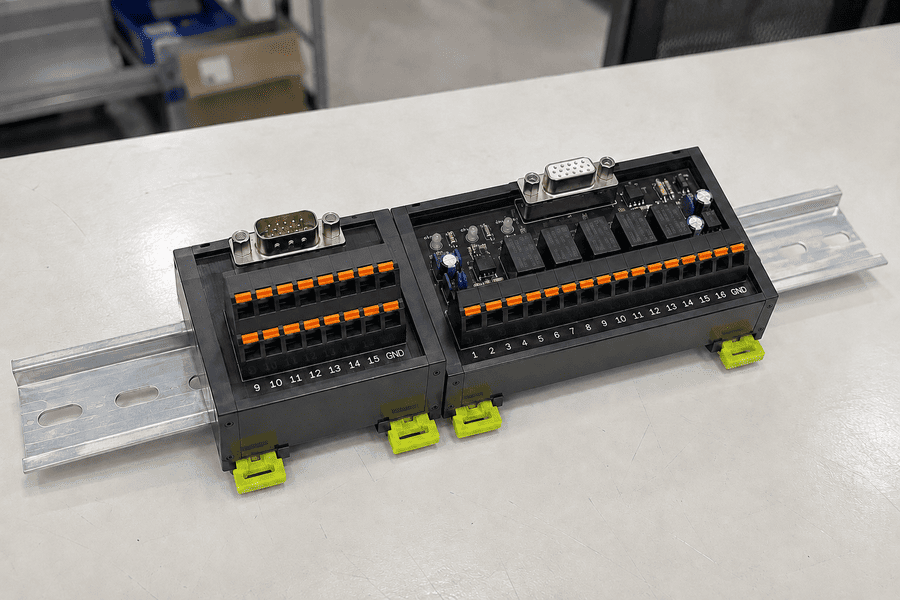
The passive-versus-active distinction is one of the most important parts of selection.
| Feature | Passive Interface Module | Active Interface Module |
|---|---|---|
| Primary purpose | Connection, breakout or distribution | Switching, isolation, protection or signal processing |
| Internal components | PCB tracks, connectors, terminals and optional indicators | Relays, optocouplers, semiconductors or signal circuits |
| Signal conversion | No | Possible, depending on the design |
| Electrical isolation | Not normally | Possible or built in |
| Operating power | Usually not required for the basic circuit | May be required |
| Selection complexity | Mainly pinout, current, voltage and wiring | Includes functional and electrical characteristics |
| Common examples | Connector-to-terminal and feed-through modules | Relay, isolated and signal-conditioning modules |
A passive interface module normally preserves the incoming electrical signal. If PLC connector pin 1 is mapped to field terminal 1, the module provides a conductive path between them. It may include LEDs, fuses or disconnect points, but these features must be shown in the circuit diagram.
Passive modules are commonly selected to reduce wiring time, improve terminal identification and make a high-density connector easier to service. They should not be described as analog-to-digital converters or protocol converters unless active conversion circuitry is actually installed.
An active module adds an electrical function beyond routing conductors. For example:
Phoenix Contact's PLC-INTERFACE range, for example, includes screw or Push-in bases with plug-in electromechanical or solid-state relays.4 This illustrates why a relay interface must be selected using more than its width or terminal count.
Depending on its construction, an interface module may provide one or more functions:
| Function | Important Limitation |
|---|---|
| Break out a 20-, 32-, 37- or 40-pin connector into accessible terminals | Pin-to-terminal mapping must match the I/O card |
| Distribute 24 VDC, 0 V or another common potential | Total bus current and branch current must be checked |
| Group signal and power connections for sensors | Channel wiring may differ for two- and three-wire devices |
| Show circuit status through LEDs | LED voltage and polarity must match the circuit |
| Protect branches through fuses or electronic protection | Fuse type, rating and indication method must be specified |
| Switch a field load through a relay | Coil voltage, contact rating, load type and switching life matter |
| Isolate or condition a signal | This requires a dedicated active circuit and cannot be assumed from the product name |
These two products are frequently confused.
| PLC I/O Module | PLC Interface Module |
|---|---|
| Part of the PLC or remote I/O system | Usually installed between the I/O card and field wiring |
| Communicates with the PLC backplane or fieldbus | May be completely passive |
| Reads inputs or controls outputs through PLC hardware | Routes, distributes, switches or conditions circuits |
| Selected according to the PLC platform | Selected according to the I/O card, cable, pinout and field requirements |
| Usually configured in PLC engineering software | Passive versions normally require no software configuration |
A connector-to-terminal interface does not add more PLC I/O points. A 16-point I/O card remains a 16-point card after it is connected to an interface module.
The phrase interface module is also used for PLC rack hardware. For example, Siemens identifies the SIMATIC S7-300 IM 365 as a paired module for rack 0 and rack 1.5
That type of module connects or expands PLC racks. It is not a DIN-rail connector-to-terminal breakout board for field wiring.
Before requesting a quotation, it helps to clarify which meaning is intended:
For terminal-block and control-cabinet suppliers, PLC interface module usually refers to the field-wiring interface, not the PLC rack module.
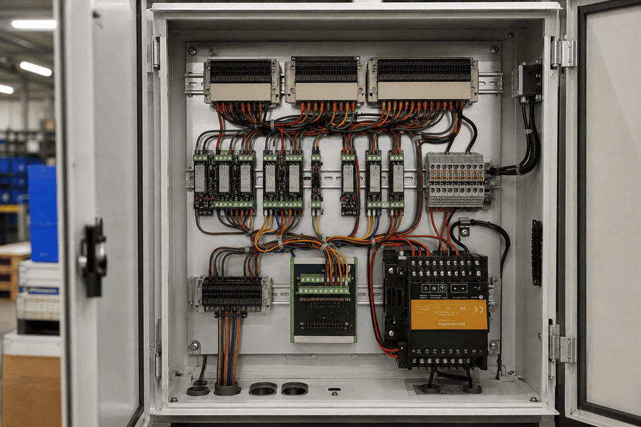
Consider a 16-point 24 VDC digital input card connected to field sensors.
16-Point PLC Digital Input Card
            |
PLC-Specific Front Connector
            |
Prewired 20- or 40-Conductor Cable
            |
16-Channel Interface Module
            |
Signal Terminals + 24 VDC + 0 V/Common
            |
Proximity Sensors, Limit Switches or Pushbuttons
The cable and interface module must preserve the I/O card's pin assignment. In a sensor-oriented design, each channel may provide a signal terminal plus shared or individual supply terminals.
The engineer still needs to verify:
Official product lineups show how specific this matching can be. Mitsubishi Electric lists connector-terminal conversion modules separately for positive-common inputs, sink-type outputs and different wiring arrangements.6 OMRON also notes that some PLC conversion units are intended for NPN wiring and are not connectable to every OMRON PLC unit.7
This is why "compatible with Mitsubishi," "compatible with OMRON" or "compatible with Siemens" is too broad. The exact PLC or I/O card model must be checked.
When I help clarify an inquiry, I begin with the circuit rather than the appearance of the housing. The following sequence gives both sides a clearer basis for checking compatibility.
First determine what the module needs to do:
If the requirement is described only as "10-in/10-out," request the internal connection diagram or explain whether the circuits are independent or commoned.
Record the complete manufacturer and part number of the PLC I/O card. Do not rely only on a family name such as S7, MELSEC, CJ, NX, ControlLogix or Micro800.
Two cards in the same PLC family may use different:
Confirm:
A clear photograph helps me identify the connector family, terminal arrangement and visible markings, but I do not use appearance as final proof of compatibility. The wiring diagram or verified pin assignment is the final reference.
Specify whether the module connects:
Then state the required number of independent channels. If common terminals are needed, identify how many channels share each common.
These terms describe current flow and common-potential arrangements. A module designed around one polarity may place LEDs, diodes, fuses or common buses in the wrong direction for the other.
For a purely passive one-to-one board, the copper tracks may not care about polarity, but the complete assembly still may. Any LED, relay coil suppression device or protective component can make polarity important.
Confirm at least:
Terminal current ratings alone do not prove that the PCB tracks, connector pins and common buses have the same capacity. The rating of the complete module is the controlling value.
Common options include:
The choice depends on conductor size, installation speed, vibration, service access and whether the field connector needs to be removable.
For a prewired PLC interface system, check:
Do not assume that a cable is straight-through. Some PLC-specific cables intentionally remap pins between the card and interface module.
Record:
A module that fits the rail may still interfere with the cabinet door, wiring duct or adjacent equipment.
For a module inside a closed control cabinet, enclosure-level protection is often more relevant than expecting the DIN-rail module itself to be IP67. Check the actual installation environment, operating temperature, pollution conditions, vibration, flame rating and any required certifications.
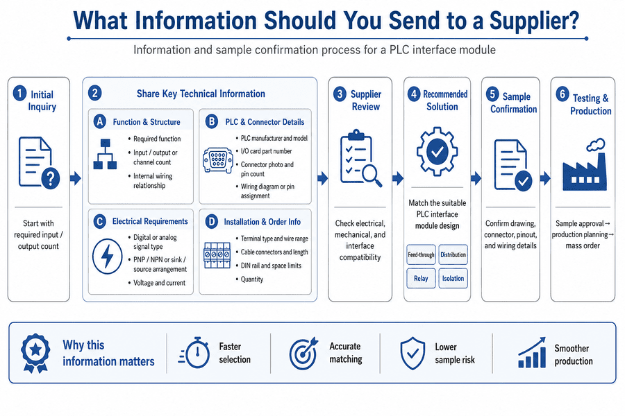
An initial inquiry can begin with the required input and output count. To move from that first question toward a reliable match, I ask for the following information as it becomes available.
| Information | Why It Matters |
|---|---|
| Required function | Distinguishes feed-through, distribution, relay and isolation designs |
| Input/output or channel count | Defines the circuit quantity |
| Internal wiring relationship | Confirms one-to-one, commoned or switched circuits |
| PLC manufacturer and model | Identifies the control platform |
| I/O card part number | Determines the actual connector and signal layout |
| Connector photo and pin count | Helps identify the physical interface |
| Wiring diagram or pin assignment | Confirms electrical compatibility |
| Digital or analog signal type | Determines circuit requirements |
| PNP/NPN or sink/source arrangement | Confirms polarity and common wiring |
| Voltage and current | Prevents electrical overstress |
| Terminal type and wire range | Confirms field installation requirements |
| Cable connectors and length | Defines the prewired connection |
| DIN rail and space limits | Confirms mechanical installation |
| Quantity | Helps determine sample and production planning |
I do not expect every customer to have a complete specification at the first contact. If only limited information is available, I suggest starting with these five items:
From these five items, I can identify which details are still missing and whether the request is likely to be a standard connection, a replacement match or a custom circuit.
Customers sometimes have an existing interface module but no complete specification. When that happens, I use photographs as a starting point, not as approval evidence. A photo can show the housing, connector, terminal count and label, but it cannot prove the internal connections or pin mapping.
A practical confirmation process is:
Collect front, side, connector and label photographs. Record module dimensions, DIN-rail mounting, terminal count and all visible model numbers.
Determine whether terminals are:
Continuity testing can help with a passive sample, but it should be performed only when the module is disconnected and safe to test.
Check mechanical mating and electrical mapping separately. A connector may mate correctly while the pin assignment is wrong.
Confirm dimensions, terminal marking, wiring diagram, connector orientation and mounting details before production.
For replacement or custom projects, sample testing is recommended before mass production. Depending on the module, testing may include:
From my side of the confirmation process, this is the point where caution matters most: a mechanically matching connector can still have the wrong electrical mapping. That is why I prefer to move from photos, to a wiring drawing, to a confirmed sample before mass production whenever compatibility remains uncertain.
PLC interface modules are widely used where many I/O points must be connected clearly and repeatedly.
| Application | How the Interface Module Helps |
|---|---|
| Packaging, filling and assembly machines | Organizes multiple sensors and solenoid-valve circuits |
| Robotics and automated cells | Groups proximity sensors, grippers, valves and status signals |
| CNC and motion-control equipment | Creates a serviceable layer for limit switches, alarms and actuator outputs |
| Control-system retrofit | Allows a new PLC-side cable or conversion interface to connect with retained field wiring |
| Sensor distribution | Groups signal, positive supply and common terminals by channel |
| Relay output interface | Separates PLC transistor outputs from field loads through replaceable switching elements |
Weidmuller identifies retrofit and migration as applications for PLC interface modules and preassembled cable systems.2
Before approving a module, confirm all applicable items below.
It creates a connection layer between a PLC I/O card and field wiring. Depending on its design, it may provide simple connector-to-terminal breakout, signal distribution, LED indication, fuse protection, relay switching or electrical isolation.
No. A PLC I/O module is part of the controller or remote I/O system and reads or controls signals. A wiring interface module is normally installed between that I/O card and field devices. A passive interface does not add I/O points or run PLC logic.
No. Passive connector-to-terminal and feed-through modules normally do not provide galvanic isolation. Isolation requires relays, optocouplers, transformers or another specifically designed isolation circuit.
No. Analog-to-digital conversion is normally performed by a PLC analog input card or a dedicated converter. A passive interface module only routes the analog conductors unless active conversion circuitry is explicitly included.
Not automatically. Compatibility depends on the I/O card, connector, pin assignment, signal type, common wiring and cable. Even modules from the same PLC brand may require different interface units.
It may mean ten independent input terminals connected one-to-one to ten output terminals, but naming practices vary. It could also describe functional I/O channels. Always check the internal wiring diagram.
A 1-in/8-out module often distributes one common supply to eight branches. An eight-channel module normally contains eight independent signal or switching circuits. They are not interchangeable.
A relay interface may be appropriate when a PLC output must switch a separate load circuit, provide galvanic separation, change contact configuration or use a replaceable switching element. Coil voltage, contact current and load type must be checked.
A photograph can identify the housing, terminals and connector, but it cannot confirm the internal wiring or pin assignment. A model number, schematic, continuity map or sample is normally required for reliable matching.
Start with the required function, input/output or channel count, PLC and I/O card model, connector and pinout, voltage/current, terminal type and quantity. If it is a replacement project, include photographs and the existing wiring diagram.
A PLC interface module is not one universal device. The name may describe a passive connector-to-terminal board, a sensor distribution module, a protected interface, a relay module, a signal isolator or even PLC rack hardware. Correct selection starts by identifying the required function.
For many control-cabinet projects, the most important questions are not only "how many inputs and outputs?" but also:
In my current conversations about these products, I have found that a short request such as "10-in/10-out" becomes much easier to evaluate once we define the circuit relationship, connector and pinout. I would rather ask one more wiring question at the beginning than let two physically similar modules be mistaken for electrical equivalents.
NITAI provides industrial terminal blocks and supports distribution and interface module projects for control-cabinet wiring. If you need help evaluating a module, send me the input/output count, PLC and I/O card model, connector photo, wiring diagram and electrical requirements. My team and I can review the available information, identify what still needs to be confirmed and help define the connection requirements before sample testing and production.
Rockwell Automation. *Bulletin 1492 I/O Wiring Systems*. Official product overview. ↩
Weidmuller. *PLC Interfaces and Preassembled Cables*. Official product overview. ↩
OMRON Industrial Automation. *Connector-Terminal Block Conversion Units*. Official product overview. ↩
Phoenix Contact. *PLC-INTERFACE Relay Technology*. Official technology and product overview. ↩
Siemens Industry Online Support. *SIMATIC S7-300 IM 365*. Official module documentation. ↩
Mitsubishi Electric. *MELSEC-L Connector and Terminal-Block Conversion Modules*. Official specifications. ↩
OMRON Industrial Automation. *XW2R PLC Connector-Terminal Block Conversion Units*. Official product lineup. ↩
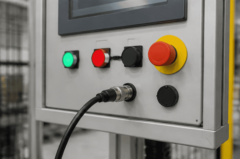
An M12 male connector 5-pin B-coded may look like a straightforward line item, but its name does not…
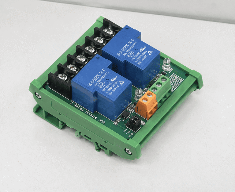
5V relay modules are used to let a low-voltage controller switch a separate electrical circuit, but many buyers…
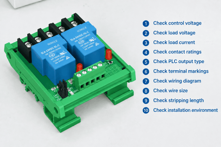
A relay module looks simple until a control cabinet fault appears after commissioning. One wrong assumption about COM,…
NITAI manufactures terminal blocks, M8/M12 waterproof connectors and industrial distribution modules for global OEMs, distributors and automation customers.
Leave a Reply