Oct 14, 2026
What Voltages Can M12 Connectors Handle?
M12 connectors can carry different voltage ratings, so a buyer cannot choose one safely from the connector size…

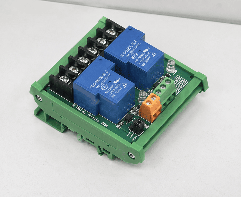
5V relay modules are used to let a low-voltage controller switch a separate electrical circuit, but many buyers misunderstand what the “5V” label actually means. I often see OEMs, PLC panel builders, and system integrators assume that a 5V module can only control a 5V load. A correct selection starts by separating the control side from the contact side.
A 5V relay module is commonly used as an interface between a low-voltage controller and a separate load circuit. The 5V rating usually identifies the relay coil or module control supply1, while the switched circuit is evaluated separately through the COM, NO, and NC contacts. Depending on the product design and datasheet, the module may control an actuator, solenoid, indicator, small motor, equipment circuit, or other electrical load. Buyers must verify input logic, coil current, contact ratings, load characteristics, isolation, wiring, and installation conditions before ordering.
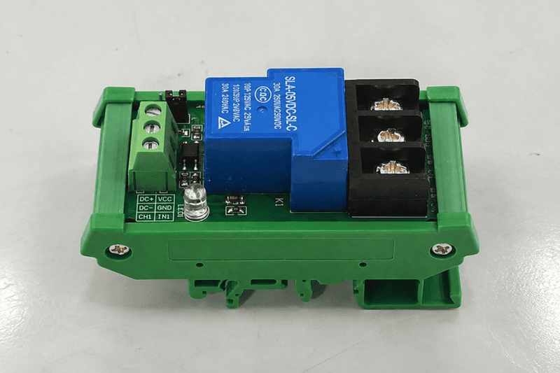
The practical value of a 5V relay module is its interface function. It can help a controller operate a circuit with different electrical characteristics. However, the relay module is not automatically compatible with every PLC, microcontroller, or load. I evaluate the controller, module, load, wiring, and environment together before recommending a product.
A 5V relay module is used to provide electrical switching and, in many designs, separation between a control signal and a load circuit.2 The controller energizes the relay coil or module input. The relay contacts then change state and connect or disconnect the load circuit according to the selected contact arrangement.
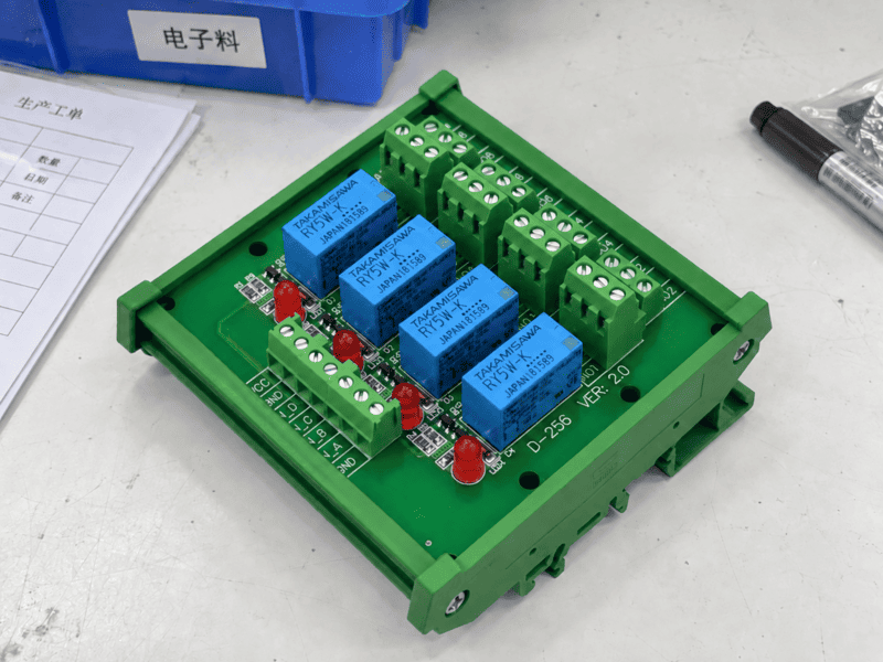
Many controllers cannot directly power a field device. A PLC output, microcontroller pin, sensor output, or interface circuit may provide only a limited voltage and current. A relay module gives the control system a practical switching interface, provided that the module input matches the controller output.
Common applications include:
I have handled customer questions where the buyer described the requirement only as “one 5V relay.” That description was not enough to identify the correct product. I needed to know whether the customer wanted a bare relay, a PCB relay module, a DIN-rail interface module, or a complete industrial relay interface with terminals and status indication.
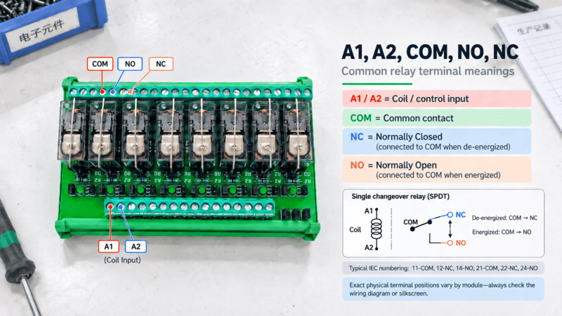
The module normally switches the circuit connected to its relay contacts. These contacts are commonly marked:
COM, NO, and NC are switching terminals. They are not three separate output-voltage sources.
When the relay is de-energized:
COM is usually connected to NC.COM is usually disconnected from NO.COM usually changes from NC to NO.For example, a 5V control circuit may activate a relay whose contacts switch a separately supplied 24V DC solenoid. In another application, the contacts may switch a lower-current indicator circuit. The module’s control voltage and the load voltage are separate selection questions.
I treat the “5V” label as a starting point, not as a complete product specification.
No. A 5V relay module does not necessarily switch a 5V load. The 5V designation usually refers to the relay coil or module input supply. The switched load depends on the contact rating, wiring arrangement, load type, and conditions stated in the specific datasheet.
I separate a relay module into two main functional areas.
| Area | Main question | Typical information to verify |
|---|---|---|
| Control side | Can the controller operate the module? | Input voltage, input current, logic level, polarity, trigger mode |
| Relay mechanism | Can the internal relay change state reliably? | Coil voltage, coil current, operating and release behavior |
| Contact side | Can the contacts switch the intended circuit? | Contact voltage, current, load category, inrush, switching frequency |
| Installation side | Can the product operate in the intended cabinet or equipment? | Terminals, mounting, temperature, spacing, enclosure, wiring access |
The control side may use a 5V supply or a 5V logic signal. The contact side may switch another voltage, but only within the product’s approved contact specifications. A buyer should never infer the allowable load from the control voltage alone.
Suppose I need a warning lamp to remain off until a fault signal activates the relay. I may connect the external supply and lamp through COM and NO. The lamp receives power only after the relay changes state.
Suppose I need a device to remain powered while the relay is inactive and disconnect after activation. I may use COM and NC. The equipment designer must confirm that this fail-state arrangement is appropriate for the application.
The contact arrangement does not create voltage by itself. The installer supplies the circuit voltage through the relevant contact path. The voltage may be 12V DC, 24V DC, 120V AC, or another value only when the relay’s datasheet and installation design support it.
A resistive load, inductive load, capacitive load, and motor load do not stress relay contacts in the same way.
A contact rating that appears suitable from the steady-state current may not be suitable for the switching event.4 I ask buyers to identify both the normal operating current and the expected inrush or transient condition.
The exact rating must come from the relevant product datasheet. I do not present a general relay rating as universally valid for every AC, DC, inductive, capacitive, or high-inrush load.
I check compatibility by comparing the controller output, relay module input, contact circuit, load behavior, and installation requirements. A module is suitable only when these conditions match the product documentation and the application design.
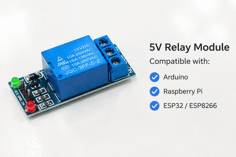
No. A 5V relay module may require a particular input voltage, current, polarity, trigger level, or common-terminal arrangement. A controller that provides a nominal 5V signal may still fail to drive the module if its output current is too low or if the module expects a different input logic condition.
I usually request the following controller information:
A microcontroller GPIO pin, for example, may produce a 5V logic level but may not be designed to drive a relay coil directly.5 The customer may need a driver circuit or a relay module with an appropriate interface stage. A PLC output may use 24V logic rather than 5V logic6, which means a nominally “5V relay module” may not be the correct direct interface.
I review the module datasheet and terminal diagram for:
I also distinguish between a relay coil specification and a complete relay module specification. A bare 5V relay may have different requirements from a module that includes a transistor driver, indicator LED, optocoupler, fuse, or terminal block.
I ask buyers to provide the load details in a structured form:
| Load detail | Why I need it |
|---|---|
| Load voltage | It determines whether the contact insulation and switching rating are suitable |
| Normal current | It provides the basic steady-state sizing reference |
| Starting or inrush current | It may exceed the normal current by a large margin |
| AC or DC | Contact behavior and arc suppression can differ |
| Resistive or inductive type | The datasheet may specify different ratings |
| Switching frequency | Frequent switching can affect service life |
| Required fail state | It determines whether NO or NC is appropriate |
| Cable length | Long wiring can increase transient and interference concerns |
| Protection method | Suppression may be required for coils, solenoids, or motors |
I do not confirm suitability from a product name alone. “5V relay module” describes only part of the product’s function.
5V relay modules need proper wiring because incorrect connections can prevent operation, damage the control output, create unwanted switching behavior, or expose the system to unsuitable contact conditions. The terminal layout and circuit design must be checked against the module documentation.
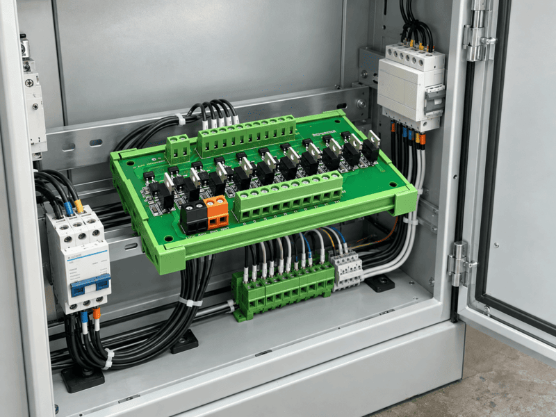
One frequent misunderstanding is that COM, NO, and NC are equivalent to positive, negative, and output terminals. They are not. They are relay contact positions. The external load circuit determines which voltage appears across those contacts.
Another common question is whether the load supply should share the same ground as the 5V control supply. The answer depends on the module architecture and the desired isolation. Some products provide an isolated control interface.8 Other products connect control and contact-related circuits through a defined common arrangement. I check the product’s circuit diagram before giving a wiring recommendation.
A third misunderstanding involves relay logic. Some customers expect the load to energize when the control signal is low, while the module is configured for a high-level trigger. The buyer must confirm the trigger mode and verify the state during startup, shutdown, fault, and power loss.
I use the following review sequence:
Identify the control supply.
I confirm whether the module requires 5V DC at a power terminal, a logic input, or both.
Identify the control reference.
I check whether the controller and module need a shared 0V or whether the input is isolated.
Identify the trigger logic.
I confirm high-level or low-level activation and the expected idle state.
Identify the contact path.
I select COM-NO or COM-NC according to the required operating and fail state.
Identify the external load supply.
I confirm that the load voltage comes from the correct circuit and does not exceed the contact specification.
Review protection.
I check whether the load requires a flyback diode, RC snubber, varistor, fuse, or another protection method.
Review physical installation.
I confirm terminal access, conductor size, clearance, enclosure conditions, and service requirements.
The exact installation should be reviewed by a qualified professional when the circuit involves hazardous voltage, safety functions, high energy, or application-specific compliance requirements.
Isolation can help reduce unwanted electrical interaction between the controller and load circuit. It may also support a more flexible system architecture. However, I do not assume that every relay module provides complete isolation just because it contains a relay.
I verify:
Isolation is a design characteristic that must be confirmed from the product documentation. It is not a guarantee that the complete installed system is safe for every application.
I select a 5V relay module supplier by evaluating technical documentation, customization capability, quality control, sample support, production consistency, and communication before price alone. A supplier should help clarify the application without making unsupported compatibility claims.
I recommend that buyers include:
NO, NC, or changeover requirement.This information allows the supplier to recommend a realistic configuration. It also reduces the risk of quoting a product that matches the keyword but fails during integration.
I ask for the following documents or confirmations:
| Supplier information | Buyer’s purpose |
|---|---|
| Datasheet | Review electrical and mechanical specifications |
| Terminal diagram | Confirm control and contact wiring |
| Dimensional drawing | Check cabinet and panel fit |
| Sample | Test the actual product before volume purchase |
| Inspection standard | Understand production quality checks |
| Material or component information | Support internal approval |
| Applicable certificates | Verify market and project requirements |
| Test reports, where available | Review stated performance evidence |
| Production lead time | Plan procurement and assembly |
| Warranty and handling process | Clarify post-delivery support |
Certifications should be treated as documents to verify for the exact model and configuration. A supplier’s general statement about certification may not cover every variant, terminal arrangement, or customized design.
At NITAI, I approach relay modules as part of the customer’s control architecture rather than as an isolated catalog item. Our broader industrial connection portfolio includes terminal blocks, PLC interface modules, relay modules, distribution modules, industrial wiring harnesses, and M8, M12, M16, and M23 waterproof circular connectors.
For OEMs and control-panel builders, I may need to coordinate:
I also explain the limits of a recommendation. I can help compare the controller interface and relay module specification, but the buyer’s qualified engineering team should approve the final circuit for the actual equipment, load, and regulatory environment.
A buyer should review more than the first sample. I suggest asking about:
A stable supplier should be able to explain how the quoted product will remain consistent across repeat orders. This concern matters to automation equipment manufacturers because a small change in terminal layout, relay component, or input circuit can affect panel wiring and field service.
A 5V relay module may switch 24V DC when the specific contact rating, load current, load type, and wiring conditions support it. The 5V value normally describes the control side. I always verify the product datasheet because DC switching capability can differ from AC capability9 and can be affected by inductive inrush.
Not always. I need to compare the PLC output voltage, output current, sourcing or sinking behavior, polarity, and module trigger requirements. Some PLC outputs may require an interface module, driver circuit, or different relay input version. I do not confirm direct compatibility from the PLC or relay name alone.
NO means normally open. The contact is open while the relay is in its normal de-energized state and closes when the relay operates. NC means normally closed. The contact is closed in the normal state and opens when the relay operates. Both work with COM as part of a changeover contact arrangement.
A relay can provide isolation between its coil and contacts, but the complete module may include shared grounds, driver components, or other connections. I verify the module circuit diagram and isolation specifications instead of assuming isolation from the product name.
I recommend sending the controller model, output details, control voltage, load voltage, current, load type, inrush information, switching frequency, contact arrangement, mounting method, environment, quantity, and documentation requirements. A wiring diagram or equipment application description can help the supplier identify compatibility questions earlier.
5V relay modules are used to connect low-voltage control systems with separately supplied load circuits. The 5V label usually identifies the relay coil or control input, not the voltage that the contacts must switch. I evaluate the controller interface, COM/NO/NC arrangement, contact ratings, load behavior, isolation, wiring, and installation environment together. I also recommend sample testing and datasheet verification before volume production.10 For OEM, PLC panel, and industrial equipment requirements, send NITAI your controller and load details so I can help review the suitable relay module configuration.
"Relay", https://en.wikipedia.org/wiki/Relay. A relay is an electrically operated switch in which the energizing coil actuates contacts in a separate circuit; consequently, the coil voltage and contact-circuit ratings describe distinct electrical functions. Evidence role: definition; source type: encyclopedia. Supports: A relay uses a control-side coil or actuator to operate contacts that switch a separate electrical circuit, with coil and contact ratings specified independently.. Scope note: This general relay definition does not establish the specifications of any particular 5V module. ↩
"Relay", https://en.wikipedia.org/wiki/Relay. Electromechanical relays may provide galvanic separation between the actuating circuit and the contact circuit because the contacts are operated mechanically rather than being electrically continuous with the coil. Evidence role: mechanism; source type: research. Supports: Electromechanical relay contacts can provide galvanic separation between the actuating coil circuit and the switched circuit.. Scope note: The conclusion applies to the relay construction and does not prove isolation for a complete module containing shared grounds, drivers, or other connections. ↩
"Relay", https://en.wikipedia.org/wiki/Relay. In a standard changeover relay, energizing the coil actuates the armature and transfers the common contact from the normally closed contact to the normally open contact. Evidence role: mechanism; source type: education. Supports: For a standard changeover relay, coil energization transfers the common contact from NC to NO.. Scope note: The operating state and contact logic must be checked for latching, solid-state, or otherwise specialized relay designs. ↩
"Inrush current", https://en.wikipedia.org/wiki/Inrush_current. Studies of relay contact behavior show that switching stress depends on transient and load-specific conditions, including inrush current and inductive energy, so steady-state current is not by itself a complete contact-selection criterion. Evidence role: mechanism; source type: paper. Supports: Inrush current, load type, and switching transients influence contact stress and service life in addition to steady-state current.. Scope note: The magnitude of the effect varies with contact material, circuit voltage, suppression, load type, and the specific relay. ↩
"GPIO Pins", https://ece353.engr.wisc.edu/gpio-pins/gpio-pins/. Microcontroller GPIO outputs are specified for bounded voltage and current conditions, whereas relay coils are inductive loads that may require substantially different drive and protection arrangements; direct connection is therefore device-dependent. Evidence role: general_support; source type: research. Supports: Microcontroller GPIO pins have specified voltage and current limits and commonly require a driver stage when operating a relay coil.. Scope note: The statement cannot determine compatibility without the electrical specifications of both the GPIO output and the relay coil. ↩
"24V DC Preferred for PLC Inputs: Safety, Reliability ...", https://www.linkedin.com/posts/gibrel-yousif-alhga-ali-256791264_why-is-24v-dc-preferred-for-plc-inputs-activity-7410417057420234752-eLPh. Industrial control systems commonly use nominal 24 V DC signal levels for PLC and field I/O interfaces, although the precise voltage range and output architecture are specified by the individual controller. Evidence role: general_support; source type: institution. Supports: 24 V DC is a common signal and supply level in industrial control systems, including PLC input and output interfaces.. Scope note: The prevalence of 24 V DC does not imply that every PLC output uses that level or that a 5V module cannot be interfaced through additional circuitry. ↩
"Relay, diodes, optocouplers - General Guidance", https://forum.arduino.cc/t/relay-diodes-optocouplers/900282. Relay-interface circuits may use diodes for inductive kick suppression, resistors for current limiting or biasing, and optocouplers for signal isolation; these components serve different functions and are not present in every module. Evidence role: mechanism; source type: education. Supports: Diodes can suppress inductive coil transients, resistors can limit or bias current, and optocouplers can provide signal isolation in relay-interface circuits.. Scope note: The source supports the functions of these components, not their inclusion in the specific module discussed. ↩
"Handson Technology User Guide 2 Channel 5V Optical ...", https://www.academia.edu/36986882/Handson_Technology_User_Guide_2_Channel_5V_Optical_Isolated_Relay_Module. A relay module provides an isolated control interface only when its complete input and output architecture maintains an isolation barrier; shared grounds or other conductive paths can defeat isolation despite the presence of a mechanical relay. Evidence role: mechanism; source type: paper. Supports: Module-level isolation depends on the interface topology, including whether an optocoupler or other isolating barrier is used and whether conductors share a reference.. Scope note: Verification requires the schematic, terminal arrangement, and rated isolation data for the particular module. ↩
"Using DC-Rated Relay Contacts for AC Load Applications", https://industrialmonitordirect.com/blogs/knowledgebase/using-dc-rated-relay-contacts-for-ac-load-applications?srsltid=AU7gw4UYbezM9Azib9wT00M9q5cpljUncHu5QYijGI67rkGTAZw_LIIm. Relay contacts often receive separate AC and DC ratings because alternating current naturally passes through current zero, whereas direct-current interruption lacks that periodic zero crossing and can sustain an arc under otherwise comparable conditions. Evidence role: mechanism; source type: paper. Supports: Relay contact ratings commonly differ for AC and DC because circuit current zero crossings and arc-extinction behavior differ between the two types of supply.. Scope note: The resulting allowable voltage and current depend on contact geometry, material, circuit time constant, and the manufacturer’s tested rating. ↩
"First article inspection", https://en.wikipedia.org/wiki/First_article_inspection. Quality-management and engineering-verification frameworks distinguish documented requirements from verification evidence and commonly use representative samples, inspection, or testing before production release. Evidence role: general_support; source type: government. Supports: Quality and engineering processes commonly require verification of specified characteristics and evaluation of representative samples before routine production or acceptance.. Scope note: The cited framework would support a general verification process, not a universal requirement for every relay-module procurement. ↩
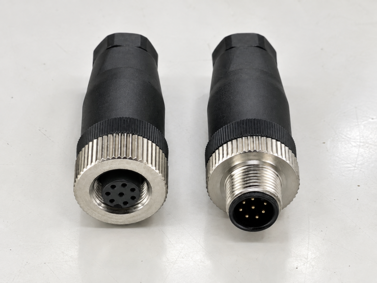
M12 connectors can carry different voltage ratings, so a buyer cannot choose one safely from the connector size…
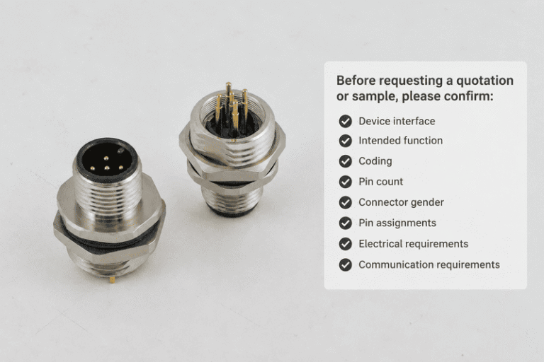
An M12 coding chart helps buyers distinguish connectors that look similar but serve different equipment functions. A wrong…
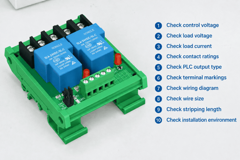
A relay module looks simple until a control cabinet fault appears after commissioning. One wrong assumption about COM,…
NITAI manufactures terminal blocks, M8/M12 waterproof connectors and industrial distribution modules for global OEMs, distributors and automation customers.
Leave a Reply