Oct 16, 2026
What Is an M12 Male Connector 5-Pin B-Coded?
An M12 male connector 5-pin B-coded may look like a straightforward line item, but its name does not…

A relay module looks simple until a control cabinet fault appears after commissioning. One wrong assumption about COM, NO, NC, coil voltage, or load wiring can damage a PLC output or create intermittent machine stops.1 I usually start with the wiring logic first, then I match the exact module diagram.
To connect wire to a relay module, identify the control/input side, output contact side, power supply, load, and terminal markings first. Wire the coil or input according to the module voltage, then route the load circuit through COM and either NO or NC based on the required switching behavior. Always verify the datasheet.
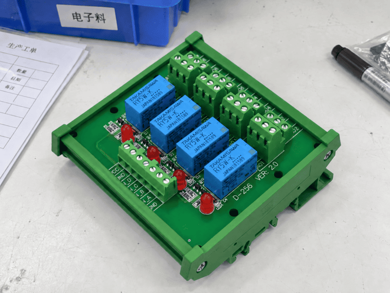
Many wiring mistakes happen because people copy a diagram from another relay module. I prefer a slower method: confirm the circuit function, check the ratings, prepare the wires correctly, and only then tighten the terminals.
A relay module can fail for reasons that are not visible during installation. The voltage may look correct, but the load type, PLC output type, terminal layout, or contact rating may be wrong. I treat every wiring job as a small selection review before I touch the terminals.
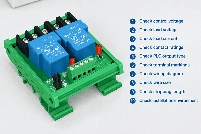
A relay module should be checked for control voltage, load voltage, load current, contact rating, PLC output type, terminal markings, wiring diagram, wire size, stripping length, and installation environment before wiring. These checks reduce the risk of PLC damage, overheated terminals, nuisance trips, and unreliable switching in industrial control panels.2
When customers ask us how to connect wires to relay modules, I often ask one question first: “What is the relay switching?” That question matters more than the terminal shape. A relay module is only useful when its control side and load side are clearly separated.
In many industrial control cabinet applications, I break the wiring review into four parts:
Control side
This side receives the PLC output, sensor signal, pushbutton signal, or controller command.
Relay coil or module input
This may be 5 VDC, 12 VDC, 24 VDC, 110 VAC, 220 VAC, or another rated voltage depending on the module.
Output contact side
This side usually includes COM, NO, and NC terminals. It switches the external load circuit.
Load circuit
This includes the power source, fuse or breaker, actuator, solenoid valve, contactor coil, indicator, motor control circuit, or other controlled device.
Before wiring, I would verify these items:
| Check item | Why it matters | What I look for |
|---|---|---|
| Control voltage | Prevents wrong coil/input voltage | 24 VDC, 12 VDC, 110 VAC, 220 VAC, etc. |
| Load voltage | Confirms contact suitability | AC or DC load voltage |
| Load current | Prevents contact overload | Running current and inrush current |
| Load type | Affects relay life | Resistive, inductive, capacitive, lamp, motor |
| PLC output type | Prevents polarity mistakes | NPN, PNP, relay output, transistor output |
| Terminal marking | Avoids wrong pin mapping | A1/A2, +/−, IN, COM, NO, NC |
| Wire gauge | Prevents loose or hot terminals | Match terminal and current rating |
| Strip length | Ensures stable clamping | Follow module datasheet |
| Protection device | Reduces fault risk | Fuse, breaker, diode, RC snubber, MOV |
| Documentation | Helps maintenance | Labels, wiring numbers, cabinet drawings |
This is a common customer issue. Two relay modules may both use COM/NO/NC markings, but the physical terminal order may differ. One module may place terminals as COM-NO-NC. Another may use NC-COM-NO. Some slim relay modules use pluggable terminal blocks. Some PLC interface relay modules use spring terminals. Some have LED indicators, test buttons, or replaceable relays.
I do not recommend wiring from memory. I recommend checking:
I am writing from a supplier perspective, not as a safety authority. For application-specific decisions, buyers should follow local electrical codes, the module datasheet, and qualified electrical evaluation.
COM, NO, and NC are often misunderstood because people see them as power terminals. That mistake causes many wrong wiring attempts. I prefer to explain them as a switching path inside the relay module, not as fixed positive, negative, live, or neutral terminals.
On a relay module, COM is the common moving contact, NO is normally open, and NC is normally closed. When the relay is not energized, COM connects to NC. When the relay is energized, COM connects to NO.3 The load circuit uses COM with either NO or NC depending on the required default state.
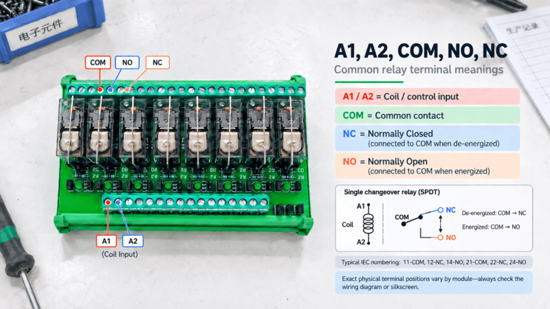
In simple terms, the relay contact behaves like a controlled switch. The coil or input side does not directly power the load in a standard electromechanical relay module. Instead, it moves an internal contact.
The basic contact behavior is:
| Relay state | COM connected to | Typical meaning |
|---|---|---|
| Relay not energized | NC | Circuit is closed in default state |
| Relay energized | NO | Circuit closes when control signal is active |
This means NO and NC are functional choices.
Use NO when the load should turn on only after the control signal appears. This is common for lamps, solenoid valves, contactor coils, and machine signals that should remain off by default.
Use NC when the load or signal should remain on until the relay operates. This may appear in alarm logic, status circuits, interlock circuits, or control logic where the default closed condition is required. However, safety-related circuits need proper safety-rated components and professional design. A normal relay module should not be assumed to be a safety relay.4
A common industrial example is a PLC controlling a 24 VDC solenoid valve through a relay module.
The load circuit may be arranged like this:
This is only one typical logic example. The exact terminal order depends on the module.
If a status lamp or monitoring input needs to be active when the relay is not energized, the circuit may use COM and NC. When the relay energizes, COM leaves NC, and the circuit opens.
This is why I tell customers not to ask only, “Where does the live wire go?” The better question is:
“What should the load do when the relay is off, and what should it do when the relay is on?”
The relay contact rating may look simple, but AC and DC switching are different. DC arcs can be harder to extinguish, especially at higher current.5 Inductive loads like coils and solenoids also create voltage spikes when switched off.6
For industrial reliability, I usually check whether the circuit needs:
A relay marked 10 A may not be suitable for every 10 A load. A resistive 10 A load and an inductive 10 A load do not stress contacts the same way.7 Buyers should review the datasheet’s load category, electrical life, and recommended protection.
The input side of a relay module seems easy because it may have only two terminals. But PLC output type, polarity, coil voltage, leakage current, and module design can change the correct wiring method. I have seen many support cases caused by mixing NPN and PNP assumptions.
The PLC or input side of a relay module should be connected according to the module’s rated input voltage and the PLC output type. For DC modules, confirm polarity and whether the PLC output is NPN sinking or PNP sourcing.8 For AC modules, confirm coil voltage, insulation, and control circuit protection before wiring.
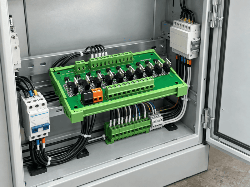
Relay module input terminals may be marked in different ways:
Some PLC interface relay modules include internal circuits such as LEDs, suppression components, or optocouplers. Because of this, polarity can matter even when the relay coil itself may seem simple.
For 24 VDC industrial control cabinets, the input wiring often involves either PNP or NPN PLC outputs.
Here is a simplified comparison:
| PLC output type | Common description | Typical current path |
|---|---|---|
| PNP output | Sourcing output | PLC output supplies +24 V to the load/input |
| NPN output | Sinking output | PLC output connects the load/input to 0 V |
| Relay output | Dry contact output | PLC output acts like a contact |
If the relay module input is designed for a specific wiring style, connecting it incorrectly may cause the relay not to operate. In some cases, it may also cause LED glow, false triggering, or output stress.
In a common 24 VDC PNP control circuit:
This arrangement is common in many European-style industrial automation systems, but it is not universal.
In an NPN control circuit:
Again, the exact connection depends on the module. I always recommend checking the module wiring diagram before production wiring.
From our pre-sales and after-sales conversations at NITAI, the same problems appear often:
For compact control cabinets, PLC interface relay modules can simplify wiring. They often provide:
However, the buyer still needs to verify voltage, current, isolation, terminal rating, and contact arrangement. A neat module does not automatically solve an incorrect circuit design.
A relay module connection can be electrically correct but mechanically weak. Loose strands, poor stripping, wrong ferrules, and unsupported cables can create heat and intermittent faults.10 In control cabinets, I have learned that the physical connection often decides whether the wiring survives vibration, maintenance, and long operation.
Reliable relay module wiring requires the correct wire gauge, proper insulation stripping length, ferrules or crimp terminals where suitable, correct terminal tightening, strain relief, clear labels, and final inspection. These practices help prevent loose connections, contact heating, broken strands, wrong maintenance reconnection, and field troubleshooting delays.
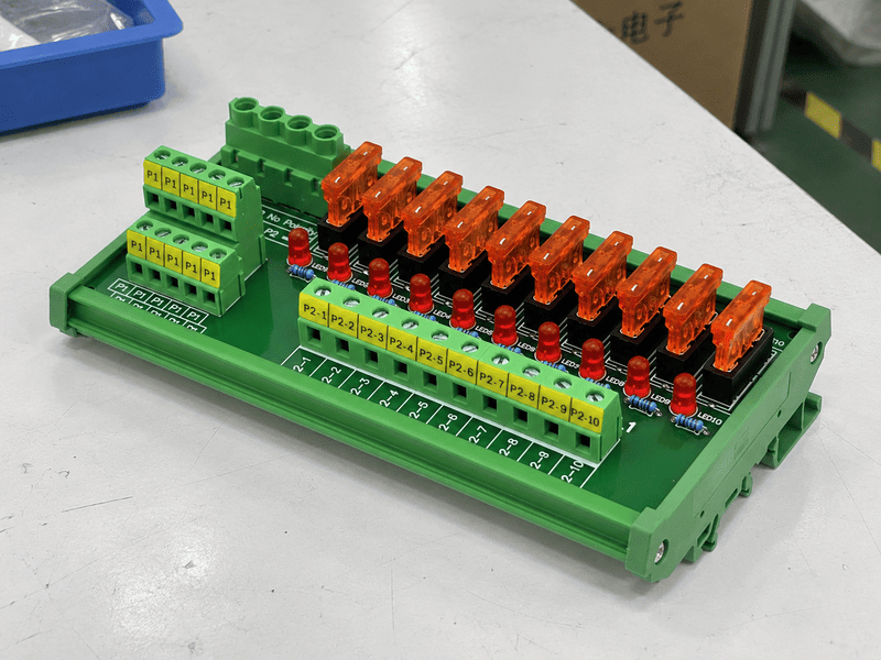
The wire should match both the current and the terminal.11 A small signal wire may be fine for the relay input side, but the load side may require a larger conductor. The terminal block must also accept that conductor size properly.
A typical industrial review includes:
For example, a relay module may accept 0.5–2.5 mm² wire, but that does not mean every circuit should use 2.5 mm². Oversized wire can be hard to clamp in small terminals. Undersized wire can overheat or loosen.
If the stripping length is too short, the terminal may clamp insulation instead of copper. If it is too long, bare copper may be exposed.12 Both conditions are bad for reliability.
I usually tell customers to follow the datasheet strip length. If the module says 7 mm, use 7 mm. If it says 10 mm, use 10 mm. Small differences can matter, especially with spring clamp terminals.
For stranded wire, ferrules are often helpful in industrial cabinets. They keep strands together and improve insertion consistency. They also reduce the chance that one loose strand escapes into a neighboring terminal.
Common options include:
A ferrule is only useful if it is crimped correctly. Poor crimping can create resistance and heating. I recommend using the correct crimping tool and checking pull strength during production setup.
Both terminal types can work well when used correctly.
| Terminal type | Strengths | Buyer should check |
|---|---|---|
| Screw terminal | Familiar, strong clamping, widely used | Torque, retightening policy, vibration |
| Spring terminal | Fast wiring, stable contact force, good for production | Wire prep, ferrule compatibility, insertion depth |
| Pluggable terminal | Easy replacement, modular maintenance | Plug retention, current rating, pin numbering |
| Push-in terminal | Fast assembly, clean cabinet wiring | Solid/ferruled wire compatibility |
For OEMs and control cabinet builders, I often recommend choosing the terminal style based on assembly process. A high-volume cabinet line may value push-in or spring terminals. A maintenance-heavy machine may prefer pluggable modules. A distributor may need broad compatibility.
Clear labeling reduces future service cost. It also protects the supplier relationship because many “product failures” are actually field reconnection mistakes.
Good labeling includes:
A simple printed wire marker can save hours during troubleshooting. In export projects, I also suggest using consistent English labels or customer-approved codes to reduce confusion across regions.
A relay module is often installed near PLCs, terminal blocks, power supplies, and field cables. This crowded environment makes mistakes easy. I have seen customers lose time because the wiring looked “almost right,” but one contact, voltage, or terminal assumption was wrong.
The most common relay module wiring mistakes are treating COM as a fixed power terminal, confusing NO and NC, using the wrong input voltage, exceeding contact ratings, ignoring PLC output type, skipping surge suppression, using poor wire preparation, and copying a diagram from a different module instead of checking the exact datasheet.
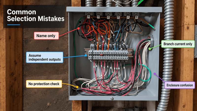
COM is not automatically positive, negative, live, or neutral. COM is the common contact. It may carry the supply side of the load circuit, or it may carry the return side, depending on the design. The correct choice depends on the circuit and applicable standards.
In many DC load examples, +24 VDC is routed through COM. But this is not a universal rule.
If a machine output should be off until the PLC signal appears, NO is usually selected. If a signal should be closed before the relay energizes, NC may be selected. The wrong choice can invert machine behavior.
This is especially important during commissioning. A valve, alarm, lamp, or permissive signal may act opposite to the expected state.
Some loads draw high current at startup. Lamps, capacitive inputs, contactor coils, and small motors may stress contacts beyond their steady-state current. A relay module contact may close successfully for a short test but fail early in real operation.
I recommend reviewing:
Inductive loads can produce voltage spikes when switched off. These spikes can damage contacts, disturb PLC signals, or create electromagnetic interference.
Typical suppression choices include:
| Load type | Common suppression method |
|---|---|
| DC coil | Flyback diode or TVS diode |
| AC coil | RC snubber or MOV |
| Contactors | Manufacturer-recommended suppressor |
| Long cable load | Review EMC and surge protection |
The best protection depends on the load and response time requirements. A qualified engineer should confirm the method for critical equipment.
Industrial control cabinets need clean separation. Signal wiring, relay coil wiring, and power load wiring should be routed thoughtfully. Poor routing can increase noise, make maintenance difficult, and create avoidable faults.
Good practice may include:
For OEM and ODM customers, I prefer a sample wiring validation before mass production. A small test can reveal wrong terminal spacing, unsuitable wire size, labeling issues, or connector mismatch.
At NITAI, we often support customers with product drawings, samples, terminal information, and wiring-related discussion before bulk supply. This does not replace the customer’s engineering approval, but it helps reduce procurement risk.
Yes, if the load voltage and current are within the relay module contact rating and the wiring follows the module datasheet. However, high-current loads, motors, and high-inrush devices may require a contactor, fuse, snubber, or other protection. I recommend engineering review for application-specific loads.
COM is not always the positive terminal. COM is the common switching contact. In some DC circuits, positive voltage may be routed through COM, but other circuits may use a different arrangement. Always check the circuit design, terminal marking, and required load behavior.
Use NO when the load should turn on only after the relay is energized. Use NC when the circuit should be closed before the relay is energized. The correct choice depends on the default state required by the machine, signal, or control logic.
The wire size should match the relay module terminal rating, load current, protection device, and cabinet standard. Many modules support a range such as 0.5–2.5 mm², but the exact value depends on the product. I recommend checking the datasheet and using ferrules for stranded wire where suitable.
Sometimes it can, but the total input current must remain within the PLC output rating. You also need to consider leakage current, response time, protection, and diagnostics. I would confirm the relay module input current and PLC output capacity before using one output for multiple channels.
A relay module should be wired by understanding the control side, contact side, power source, load path, and COM/NO/NC function before inserting any wire. I would never rely on one universal diagram because terminal layouts, PLC output types, and load requirements vary. For industrial buyers, reliable wiring also depends on wire preparation, ferrules, labeling, and supplier documentation. If you need relay modules, terminal blocks, wiring harnesses, or PLC interface solutions for OEM production, NITAI can support samples, drawings, customization, and stable bulk supply.
"Troubleshooting a PLC Output",
. A PLC application manual or industrial-control training source documents that digital outputs are limited by specified voltage and current ratings, supporting the general claim that incorrect relay-module wiring can damage outputs or cause operational faults. Evidence role: general_support; source type: institution. Supports: PLC digital outputs have defined voltage/current limits and may malfunction or be damaged when connected to inappropriate loads or wiring arrangements.. Scope note: This would support the mechanism and risk generally, not prove the specific commissioning failures described by the author. ↩"Group Safety Standard: IEC 60204-1: 2016", https://www.idec.com/en-ca/solutions/safety/law/iso-iec/iec60204. Industrial-control-panel standards such as IEC 60204-1 and UL 508A require attention to component ratings, conductor sizing, overcurrent protection, and terminal suitability, supporting the checklist as a risk-control practice. Evidence role: general_support; source type: institution. Supports: Industrial-control standards require equipment, conductors, protection devices, and terminals to be selected according to ratings and installation conditions.. Scope note: Standards support the checklist contextually; they do not quantify the exact reduction in PLC damage or nuisance trips. ↩
"Electrical contact", https://en.wikipedia.org/wiki/Electrical_contact. A neutral relay reference defines normally closed contacts as closed in the de-energized state and normally open contacts as closed only after actuation, supporting the stated COM-NC and COM-NO behavior. Evidence role: definition; source type: encyclopedia. Supports: The meaning of common, normally open, and normally closed contacts in an electromechanical relay.. ↩
"ISO 13849-1:2015 - Safety of machinery", https://www.iso.org/standard/69883.html. Machinery-safety standards such as ISO 13849-1 distinguish safety-related control parts and require validated performance levels, supporting the statement that an ordinary relay module should not be assumed to function as a safety relay. Evidence role: expert_consensus; source type: institution. Supports: Safety-related control functions require components and architectures evaluated to recognized machinery-safety standards, rather than ordinary relays assumed to be safe by default.. Scope note: The source would support the safety principle generally; the suitability of a particular module still depends on its certification and application design. ↩
"Fundamental characteristics of arc extinction by magnetic ...", https://ieeexplore.ieee.org/document/7031036/. Research on switching arcs explains that alternating current naturally reaches current-zero crossings that assist arc extinction, whereas direct current lacks this periodic aid, supporting the claim that DC contact switching can be more demanding. Evidence role: mechanism; source type: paper. Supports: DC arcs are more difficult to interrupt than AC arcs in comparable switching contexts because AC current periodically crosses zero.. ↩
"Flyback diode", https://en.wikipedia.org/wiki/Flyback_diode. Educational circuit references on inductors and flyback protection explain that interrupting current through a coil can create a transient voltage, supporting the statement that solenoids and other inductive loads can produce switch-off spikes. Evidence role: mechanism; source type: education. Supports: An inductor resists sudden changes in current and can generate a voltage transient when current is interrupted.. ↩
"Utilization categories", https://en.wikipedia.org/wiki/Utilization_categories. Switching-device standards and relay engineering references distinguish utilization categories and contact ratings by load characteristics, supporting the statement that a 10 A resistive load and a 10 A inductive load may impose different contact stress. Evidence role: general_support; source type: institution. Supports: Contact ratings and utilization categories vary by load type, including resistive and inductive loads.. Scope note: This supports the selection principle; the acceptable load for a specific relay still depends on that relay’s datasheet. ↩
"What is the difference between NPN and PNP?", https://maplesystems.com/faq/what-is-the-difference-between-npn-and-pnp/?srsltid=AU7gw4VqwdgmEF5D4OdvxFaFdaGUW9CafIDWUcxWfiayvaeDnvK6GNK1. Industrial-automation teaching materials define sourcing outputs as supplying positive voltage to a load and sinking outputs as completing the path to common, supporting the need to verify PNP/NPN output type and polarity for DC relay-module inputs. Evidence role: definition; source type: education. Supports: PNP outputs are commonly described as sourcing outputs, while NPN outputs are commonly described as sinking outputs in DC control circuits.. Scope note: The definitions support the wiring distinction generally; individual module wiring still depends on the product circuit. ↩
"PLC Output Modules: Can They Energize Relays Directly?", https://industrialmonitordirect.com/blogs/knowledgebase/can-plc-output-modules-power-relays-directly-beginner-guide?srsltid=AU7gw4WVoDT3soFVU_pdbR-ajNoNgPvZwXQGwBHfPi0a5MrV-7H5LNM2. PLC hardware manuals specify maximum output-current ratings for transistor outputs, supporting the claim that a relay coil or module input exceeding that capacity can overload the PLC output. Evidence role: general_support; source type: institution. Supports: PLC transistor outputs are rated for maximum load current, and connected relay coils or inputs must remain within that rating.. Scope note: The source would establish the rating principle; actual overload depends on the specific PLC output and relay input current. ↩
"NASA-STD-8739.4A PDF", https://s3vi.ndc.nasa.gov/ssri-kb/static/resources/nasa-std-8739.4a.pdf. Government wiring-workmanship standards such as NASA-STD-8739.4 treat strand control, insulation clearance, crimp quality, and strain relief as reliability requirements, supporting the statement that poor wire preparation can cause heat or intermittent faults. Evidence role: general_support; source type: government. Supports: Accepted wiring-workmanship criteria address strand control, insulation stripping, crimp quality, and mechanical support as factors in reliable electrical terminations.. Scope note: Aerospace workmanship standards provide conservative contextual support and may exceed ordinary cabinet-building requirements. ↩
"1910.304 - Wiring design and protection.", http://www.osha.gov/laws-regs/regulations/standardnumber/1910/1910.304. Electrical-code guidance on conductor ampacity and terminal limitations supports the principle that a wire must be suitable for both the circuit current and the terminal to which it is connected. Evidence role: general_support; source type: government. Supports: Electrical installation rules require conductors and terminations to be selected according to current, ampacity, temperature, and terminal limitations.. Scope note: The source supports the general selection principle; exact conductor size depends on local code, installation conditions, and the module datasheet. ↩
"NASA-STD-8739.4A PDF", https://s3vi.ndc.nasa.gov/ssri-kb/static/resources/nasa-std-8739.4a.pdf. Wire-termination workmanship standards specify limits on insulation clearance and exposed conductor near terminals, supporting the explanation that too little strip length can impair clamping while too much can expose bare copper. Evidence role: mechanism; source type: government. Supports: Wire-termination workmanship criteria specify proper insulation strip length to avoid insulation under the contact area and excessive exposed conductor.. Scope note: The standard supports the workmanship mechanism generally; the exact strip length must come from the relay-module or terminal manufacturer. ↩
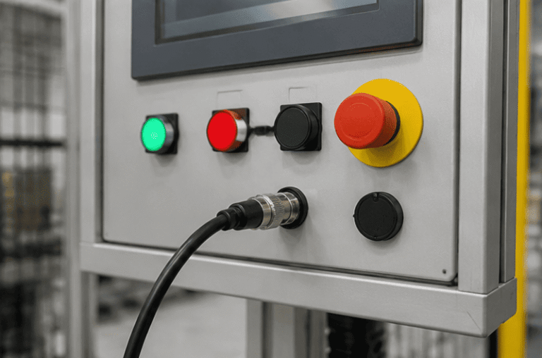
An M12 male connector 5-pin B-coded may look like a straightforward line item, but its name does not…
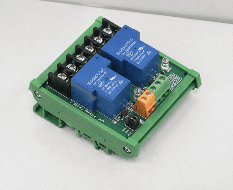
5V relay modules are used to let a low-voltage controller switch a separate electrical circuit, but many buyers…
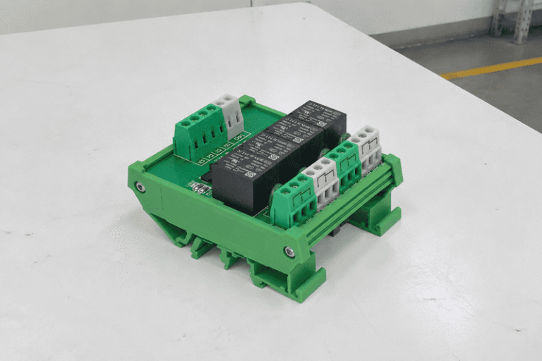
A relay module can look simple in a photo, but that simplicity often causes sourcing mistakes. I often…
NITAI manufactures terminal blocks, M8/M12 waterproof connectors and industrial distribution modules for global OEMs, distributors and automation customers.
Leave a Reply