Oct 17, 2026
How Do I Choose the Right M8 8 Pin Female Connector for My Equipment?
An M8 8 pin female connector can look like the right replacement on a purchasing list and still…

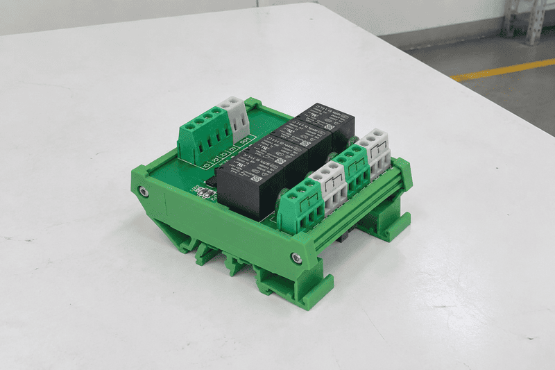
A relay module can look simple in a photo, but that simplicity often causes sourcing mistakes. I often see buyers identify only the blue relay body or terminal block, then later discover the coil voltage, contact type, or mounting style is wrong. The safer solution is to use appearance as the first clue, not the final specification.
A relay module usually looks like a compact assembly with one or more relay bodies mounted on a base or PCB, input and output terminals, a marking label, sometimes an LED indicator, and often a DIN rail mounting structure. However, buyers should confirm voltage, contact configuration, channel count, terminal type, and installation method before purchase.
When I help customers identify a product from a photo, I do not stop at the visible shape. I look at the markings, terminal layout, wiring direction, and mounting details. Those small details often decide whether the part is suitable for a PLC cabinet, machine control panel, or industrial automation device.
A relay module usually has recognizable parts, but not every model shares the same layout. This creates a problem for buyers who search by image only. One module may look close to another, yet the internal function or wiring arrangement may be different.
A relay module usually includes a relay body, socket or base, terminals, LED indicator, label markings, and a mounting structure. Some are single-channel PCB modules, while others are slim DIN rail interface modules used in PLC control cabinets.1 The visible structure helps identification, but it does not prove interchangeability.
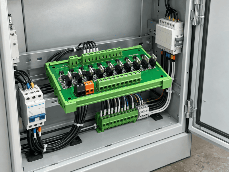
When a customer sends me a photo, I usually zoom in on the following parts before I discuss replacement or quotation:
In my daily product work, I have learned that the label and terminal markings matter more than the color of the relay. A buyer may send a photo of a slim relay interface module and say, “I need this blue relay.” But the blue part is only one component. The full assembly may include a socket, jumper bridge, LED circuit, suppression component, and DIN rail housing.
| Appearance type | Typical visual features | Common application |
|---|---|---|
| Single relay on PCB | One relay body, screw terminals, small board | Simple equipment control, test fixtures |
| Multi-channel relay board | 2, 4, 8, or more relays on one PCB | Automation panels, signal switching |
| Slim DIN rail relay module | Narrow housing, plug-in relay, LED, terminal base | PLC cabinets and control panels |
| PLC relay interface module | Compact multi-channel interface, cable or terminal connection | PLC output expansion and signal isolation |
| Plug-in relay with socket | Separate relay inserted into a base | Maintenance-friendly panel wiring |
A relay module may look like a basic switching device, but its specification determines whether it works safely and correctly in a system. I usually ask customers to confirm:
I have seen two modules look almost identical in a photo, but one used a 24VDC coil and another used a 220VAC coil. They were not interchangeable. That is why I always recommend using visible identification together with the datasheet, wiring diagram, and application requirement.
Many buyers use the same words for different parts, and this creates confusion during sourcing. I often receive inquiries where the buyer says “relay module,” but the photo shows only a relay socket or a plug-in relay. Clear naming saves time.
A relay is the switching component itself.2 A relay socket is the base that connects the relay to wiring. A relay module is an assembled unit with relay, base or PCB, terminals, and sometimes LED or protection parts. A PLC relay interface module is designed specifically for PLC signal connection and cabinet wiring.
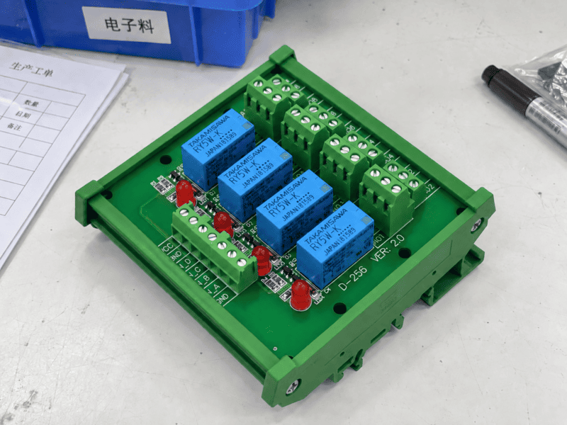
| Item | What it looks like | What it usually includes | Buyer risk if confused |
|---|---|---|---|
| Relay | Small rectangular plug-in or PCB component | Coil and contacts inside housing | Buyer may miss socket or wiring base |
| Relay socket | Base with terminals and relay pins | Connection base only | Buyer may buy socket without relay |
| Relay module | Relay plus PCB/base, terminals, LED, housing | Complete switching assembly | Buyer must verify voltage and contact type |
| PLC relay interface module | Slim DIN rail interface, often multi-channel | PLC-friendly wiring and relay switching | Buyer must verify PLC wiring and pinout |
When I prepare a quotation, I need to know whether the customer wants:
These are not the same product. They may use similar relay elements, but the mechanical design, terminal layout, and wiring method can be very different.
A customer once sent me a photo of a narrow DIN rail product and asked for “the same relay.” At first glance, the visible relay looked standard. But after I checked the photo carefully, I noticed:
The customer did not need only the relay. He needed the complete interface module for a control cabinet. If he had purchased only the relay body, his technician would still need the matching base and wiring accessories.
To avoid wrong quotations, I usually ask buyers to send:
This information lets a supplier check the visible product and the electrical specification together. I consider that approach more reliable than asking, “Can you supply the relay in this picture?”
Two relay module products can look almost identical from the front, which is why buyers should be careful. The problem becomes worse when photos are low-resolution or when the model label is hidden inside a cabinet.
Two relay modules can look the same but differ in coil voltage, contact configuration, contact rating, channel count, terminal arrangement, circuit protection, and mounting dimensions. These differences affect selection, wiring, and replacement. Buyers should verify the datasheet and application requirements before treating similar modules as interchangeable.
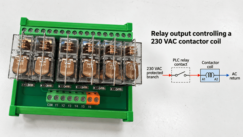
A module’s shape can help recognition, but many important specifications are not obvious at first glance. I always check these points before confirming a selection:
| Specification | Why it matters | Example difference |
|---|---|---|
| Coil voltage | Controls relay activation | 24VDC vs 220VAC |
| Contact form | Defines switching behavior | 1NO, 1NC, 1CO, 2CO |
| Contact rating | Defines load capacity | 5A vs 10A |
| Number of channels | Affects wiring density | 1-channel vs 8-channel |
| Terminal type | Affects installation method | Screw vs spring clamp |
| Mounting | Affects cabinet design | DIN rail vs PCB |
| Indicator circuit | Affects troubleshooting | With LED vs without LED |
| Suppression circuit | Affects coil protection | Diode, RC, or none depending on model |
In industrial automation, 24VDC control is common in PLC cabinets.3 However, many machines also use AC control circuits or special voltage requirements. A photo cannot always prove this. The relay body may show the coil voltage, but the marking can be covered or blurred.
If a buyer replaces a 24VDC module with a 12VDC module, the relay may not operate correctly.4 If the replacement has the wrong AC/DC coil type, the system may fail during commissioning. I do not recommend guessing here.
The contact layout also matters. A relay module may provide:
A module with the same housing width may have different contact forms.5 If a machine design depends on a normally closed safety-related signal, the wrong contact form can create a serious functional problem. For application-specific decisions, I always suggest that the buyer’s qualified electrical engineer review the circuit.
Even if the electrical rating matches, the module may not fit the wiring style. Some control panels need front-entry spring terminals for fast wiring. Others use screw clamps because maintenance teams prefer them. Some PLC interface modules use ribbon cable or pre-wired connectors.
For OEM buyers, this detail affects production efficiency. A lower-cost product may create higher wiring labor if the terminal direction does not match the cabinet design. That is why I view terminal layout as both a technical and procurement factor.
From a supplier perspective, I do not treat “similar looking” as “same.” I treat it as a request for confirmation. I usually compare:
This method reduces wrong samples and avoids unnecessary redesign for the customer.
A relay module often carries printed markings that are more useful than its color or shape. The problem is that buyers sometimes send only a front photo, while the most important information may be printed on the side, top, or relay body.
Before buying a relay module, check the model number, coil voltage, contact rating, wiring diagram, terminal numbers, brand or supplier code, channel count, and mounting information. These markings help suppliers confirm whether the product matches the control circuit, load requirement, and cabinet installation method.
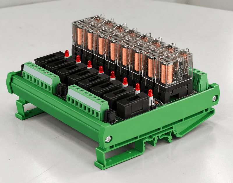
When a customer wants help identifying a module, I prefer three to five photos. The best set includes:
These photos help me understand both the product and the installation environment.
Many industrial relay interface products use recognizable terminal numbers, but buyers should still verify the exact datasheet.
| Marking | Common meaning | Note |
|---|---|---|
| A1 / A2 | Coil input terminals | Polarity may matter for DC modules with LED or diode |
| 11 / 12 / 14 | Changeover contact group | Common, NC, NO in many layouts |
| 21 / 22 / 24 | Second contact group | Often used in 2CO relays |
| + / - | DC input polarity | Important when LED or protection circuit exists |
| IN / COM | Control input reference | Common on some PCB relay boards |
| NO / NC / COM | Contact terminal labels | Common on general relay boards |
The small diagram printed on the module is one of the most useful identification clues. It shows how the coil and contacts connect internally. It may also show polarity, LED indicator, freewheel diode, or other protection elements.
If the module includes a diode, polarity matters. If the buyer reverses polarity on a DC input module, the relay may not energize.6 If the module includes an LED, the user can visually confirm input status during troubleshooting. These are small features, but they affect installation and maintenance.
For B2B sourcing, I suggest buyers prepare a short specification sheet instead of relying only on photos.
A good inquiry does not need to be complicated. It only needs to remove the main uncertainties.
Here is the checklist I recommend:
At NITAI, our role is to help customers narrow the selection based on actual project needs. For certificates, compatibility, and performance data, I always recommend checking the specific product documentation rather than assuming one module represents all products in the category.
A relay module used in a PLC control cabinet must match more than the relay appearance. The risk is that a product may fit the DIN rail but not fit the control logic, wiring method, or maintenance preference of the cabinet builder.
To choose the right relay module for a PLC control cabinet, confirm PLC output type, control voltage, contact form, load rating, channel count, terminal style, module width, wiring diagram, indicator needs, and documentation. Cabinet builders should verify these details against the PLC and load requirements before ordering samples.
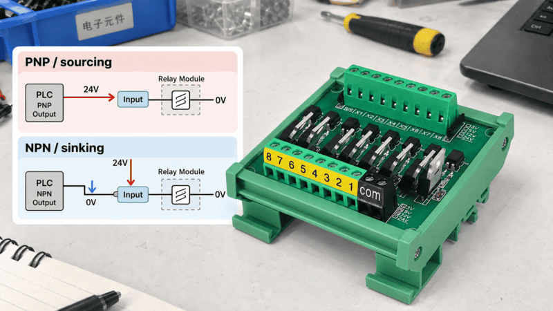
PLC outputs are not all the same. Some are transistor outputs, some are relay outputs, and some use sourcing or sinking logic. The relay interface product must match the control side. I often ask customers:
A standard photo cannot answer these questions. The PLC model and wiring diagram usually can.
The output contact side connects to the load or another control circuit. The load may be:
The contact rating must be suitable for the load type. Resistive and inductive loads behave differently.7 For higher-risk or application-specific loads, I recommend that a qualified engineer evaluate the circuit and protection method.
PLC cabinet builders often care about installation time. A good relay interface design can make wiring cleaner and faster. Buyers may compare:
| Cabinet requirement | Suitable feature to consider |
|---|---|
| High wiring density | Slim DIN rail module |
| Fast field wiring | Spring clamp terminal8 |
| Maintenance familiarity | Screw terminal |
| PLC output grouping | Multi-channel interface module |
| Easy troubleshooting | LED indicator |
| Quick replacement | Plug-in relay design |
| OEM production repeatability | Stable model and documentation |
In my experience, importers and OEM buyers often focus first on unit price. That is understandable. However, cabinet wiring labor, rework risk, and sample approval time also affect total cost. A slightly better terminal layout may save more time during assembly than a small price reduction saves during procurement.
For new projects, I usually recommend sample confirmation before batch orders. The sample check should include:
This process is practical for overseas B2B buyers because it reduces communication errors before mass production. It also gives the buyer a chance to confirm whether custom labeling, private brand packing, or wiring accessories are needed.
A standard module may be enough for many control cabinets. Customization may make sense when the buyer needs:
As a manufacturer of industrial connection products, NITAI can support OEM/ODM discussions, sample development, and production planning. Still, I always treat customization as a specification-driven process. The correct design should start from wiring needs, voltage, contact logic, and installation constraints.
Yes, you can often make an initial identification from a photo, especially if the image shows the relay body, terminals, label, and wiring diagram. However, I do not recommend confirming purchase by photo alone. You should also verify voltage, contact type, channel count, terminal layout, and mounting dimensions.
No. A relay is usually the switching component itself. A relay module is a more complete assembly that may include a relay, base or PCB, terminals, LED indicator, protection circuit, and mounting structure. Buyers often confuse these terms, so I suggest sending photos and required specifications together.
You should send clear photos, model markings, control voltage, contact form, load rating, channel count, terminal type, mounting method, quantity, and any documentation requirements. If the module is used in a PLC cabinet, you should also share the PLC output type and wiring requirement.
Not always. Similar-looking products may have different coil voltages, contact ratings, wiring diagrams, terminal layouts, or mounting dimensions. I recommend checking the datasheet and sample before replacement. For critical applications, a qualified electrical professional should confirm the selection.
No. Many industrial interface modules include LED indicators, but not all relay modules have them.9 Some simple PCB modules or socket assemblies may not include status indication. You should confirm the product specification if LED status display is important for troubleshooting or cabinet maintenance.
A relay module usually looks like a relay body combined with terminals, a base or PCB, markings, and sometimes an LED indicator or DIN rail housing. However, appearance is only the first step. I always recommend confirming voltage, contact type, channel count, terminal style, wiring diagram, and mounting method before purchase. If you need help identifying a module, send us a clear photo, wiring requirement, voltage, contact type, channel count, terminal type, and mounting needs. NITAI can help you review the selection and prepare the right quotation or custom option.
"DIN rail", https://en.wikipedia.org/wiki/DIN_rail. IEC 60715 specifies the dimensions of top-hat (T-profile) DIN rails used for the mechanical support and mounting of electrical devices in switchgear and controlgear assemblies, providing the dimensional basis for DIN rail relay module designs. Evidence role: definition; source type: institution. Supports: That DIN rail mounting is a recognized and standardized installation method for relay interface modules in industrial control cabinets. Scope note: IEC 60715 covers mounting rail geometry only; it does not classify relay module form factors or define the distinction between PCB and DIN rail module types. ↩
"Relay", https://en.wikipedia.org/wiki/Relay. According to standard electrical engineering references, a relay is an electrically operated switch in which an electromagnet energized by a control circuit mechanically actuates one or more sets of contacts to switch a separate load circuit. Evidence role: definition; source type: encyclopedia. Supports: That a relay is an electrically operated switch in which a control signal activates a coil to open or close one or more sets of contacts. Scope note: Definitions vary slightly across sources; solid-state relays operate without mechanical contacts, so the definition applies most directly to electromechanical relay types discussed in this article. ↩
"IEC 61131", https://en.wikipedia.org/wiki/IEC_61131. IEC 61131-2 and related industrial automation standards document 24VDC as the widely adopted control supply voltage for programmable logic controller input/output circuits in industrial environments. Evidence role: expert_consensus; source type: institution. Supports: That 24VDC is the predominant control voltage in industrial PLC cabinet applications. Scope note: Standards documents define permissible voltage ranges rather than prescribing 24VDC exclusively; actual prevalence is an industry convention rather than a mandated requirement. ↩
"Relay", https://en.wikipedia.org/wiki/Relay. IEC 61810-1, which specifies requirements for electromechanical elementary relays, defines must-operate voltage and must-release voltage as key coil parameters, establishing that reliable switching depends on the applied voltage falling within the rated operating range. Evidence role: mechanism; source type: institution. Supports: That relay coils have defined must-operate and must-release voltage thresholds, and applying a voltage outside the rated range will result in failure to energize or unreliable switching. Scope note: IEC 61810-1 addresses elementary relays; relay modules incorporating additional circuitry may have different effective voltage tolerance characteristics as specified by the module manufacturer. ↩
"About MOSFET Relay Module | ARATAS Americas,formerly ...", https://components.omron.com/us-en/products/relays/mosfet-relays/mosfet-relay-module_features. Relay product standards such as IEC 61810-1 specify coil and contact parameters independently of mechanical housing dimensions, allowing manufacturers to produce relays with identical footprints but differing contact forms (e.g., 1NO, 1NC, 1CO) within the same product family. Evidence role: general_support; source type: paper. Supports: That relay housing dimensions and contact configuration are independently specified parameters, meaning physically similar relays may have different switching arrangements. Scope note: This is an inference from the structure of relay standards rather than a direct empirical study; specific product families should be verified against manufacturer datasheets. ↩
"Flyback diode", https://en.wikipedia.org/wiki/Flyback_diode. In relay coil protection circuits, a flyback diode is connected in reverse bias across the coil to suppress the back-EMF voltage spike upon de-energization; because the diode is polarized, reversing the DC supply polarity causes the diode to conduct continuously, preventing current from building up in the coil and thus blocking relay operation. Evidence role: mechanism; source type: education. Supports: That a flyback (freewheeling) diode connected across a relay coil is a polarized component that blocks current flow when DC supply polarity is reversed, preventing coil energization. Scope note: The exact behavior depends on circuit design; some modules include additional protection components such as varistors or RC snubbers that may alter the response to reversed polarity. ↩
"Utilization categories", https://en.wikipedia.org/wiki/Utilization_categories. IEC 60947-5-1, which governs low-voltage switchgear and controlgear, defines distinct utilization categories for resistive and inductive AC and DC loads, reflecting the differing arc energy and contact wear characteristics associated with each load type. Evidence role: mechanism; source type: institution. Supports: That inductive loads impose different electrical stress on relay contacts compared to resistive loads, requiring derating or arc suppression consideration. Scope note: The standard addresses contactors and control circuit devices broadly; specific relay module derating factors depend on individual product datasheets. ↩
"Push-in vs spring clamp terminals: faster installation and ...", https://mktg.idec.com/en-gb/article/push-in-vs-spring-clamp-terminals-faster-installation-and-safer-connections. IEC 60947-1, covering general rules for low-voltage switchgear and controlgear, and IEC 60999-1, addressing connecting devices for copper conductors, both recognize spring-type clamping units as a defined terminal connection technology alongside screw-type terminals. Evidence role: definition; source type: institution. Supports: That spring clamp (spring cage) terminals are a standardized connection technology used in industrial control equipment, recognized alongside screw terminals in relevant standards. Scope note: Standards define test and performance requirements for terminal types rather than prescribing their use in specific applications; the selection between spring and screw terminals remains an application and design preference. ↩
"Relay Module Status - General Electronics", https://forum.arduino.cc/t/relay-module-status/450431. IEC 61810-1 and related relay product standards do not mandate LED status indication as a required feature of electromechanical relays or relay modules; its inclusion is a manufacturer design choice, and its presence or absence is specified in individual product datasheets. Evidence role: general_support; source type: institution. Supports: That LED coil status indication is a functional feature present on many but not all relay interface modules, serving a diagnostic role in industrial control systems. Scope note: No comprehensive industry survey data on the prevalence of LED indicators across relay module product categories was identified; the claim reflects general product observation rather than a statistically documented industry norm. ↩
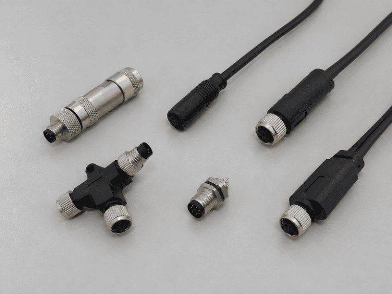
An M8 8 pin female connector can look like the right replacement on a purchasing list and still…
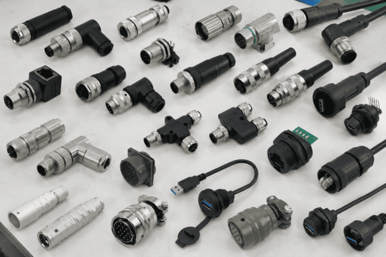
Connector types can look interchangeable in a catalog, but a familiar shape does not tell me whether two…

A coded and B coded M12 connectors can look similar in a purchasing list, but choosing the wrong…
NITAI manufactures terminal blocks, M8/M12 waterproof connectors and industrial distribution modules for global OEMs, distributors and automation customers.
Leave a Reply