Oct 16, 2026
What Is an M12 Male Connector 5-Pin B-Coded?
An M12 male connector 5-pin B-coded may look like a straightforward line item, but its name does not…

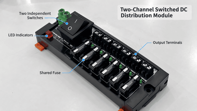
A DC power distribution module accepts an existing DC supply and divides it into multiple output circuits through a compact terminal assembly. Depending on its design, it may also add switches, status LEDs, a common fuse, individual branch protection, or electronic circuit breakers. It distributes DC power; it does not normally convert AC to DC or regulate the voltage.
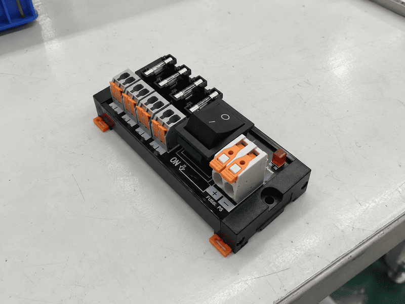
A compact two-channel module can combine one DC input, two switched positive-and-negative output pairs, status indication, and shared input protection on one rail-mounted assembly.
When customers ask us for a “DC power module,” I first confirm what they actually need the device to do. Some need an AC-to-DC power supply. Others already have 12 VDC, 24 VDC, or another DC source and only need a safe way to divide that power between two or more loads. Those are different products, even though the names used in inquiries are often similar.
This distinction matters because a distribution module cannot correct an unstable supply, increase available current, or automatically protect every output independently. The circuit topology, current limits, fuse arrangement, terminal capacity, load inrush, and enclosure all have to match the application.
This guide explains how a DC power distribution module works, using a two-channel spring-clamp configuration as a practical example. It also shows how to read the ratings and decide whether common protection, branch protection, or an electronic circuit breaker is appropriate.
A DC power distribution module creates several usable branch connections from one DC input while keeping the wiring organized. It may switch, indicate, or protect those branches, but it cannot create more power than the upstream supply can provide.
In practical control-panel work, “distribution module” describes a function rather than one universal construction. A module may be a simple passive distribution point, or it may combine distribution with switching, indication, fusing, or electronic protection. For that reason, the internal circuit arrangement matters more than the product name alone.
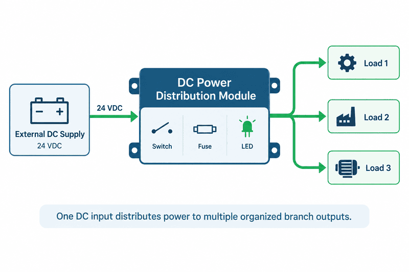
The upstream supply creates the required DC voltage. The distribution module then routes that voltage to separate loads and may add switching, indication, and protection along the path.
| Stage | Main function | What it does not guarantee |
|---|---|---|
| AC-to-DC power supply | Converts mains AC into regulated DC | Multiple protected output branches |
| DC source or battery | Provides the available DC voltage and current | Organized circuit distribution |
| DC power distribution module | Divides one DC input into several output circuits | Voltage conversion or unlimited current |
| Switch | Opens or closes a selected circuit | Overcurrent protection unless specifically designed for it |
| Fuse or circuit breaker | Interrupts excessive current under defined conditions | Correct wire sizing or load compatibility |
| Connected load | Uses the distributed power | Protection for the upstream wiring |
In practice, the basic power path is:
DC source → input connection → protection → branch switch or control element → output terminal → load
Some products omit the switch. Some use one common fuse. Others place a fuse or electronic breaker on every channel. That internal difference is more important than the product name printed in a catalog.
A two-channel switched module takes one DC input and sends it to two separately controlled output pairs. In the reference configuration used here, one shared replaceable fuse protects the input path, two double-pole rocker switches disconnect both conductors of their respective loads, and LEDs show input and switched-output status.
In this topology, the input fuse is shared by both channels. Each rocker switch controls the positive and negative conductors of one output, while the red and green LEDs indicate electrical state rather than actual load health.
The two-channel reference configuration has the following current path:
The following values are shown as an example configuration to explain the selection logic. Always verify the actual product datasheet before final selection or installation.
| Parameter | Two-channel reference configuration | Why it matters |
|---|---|---|
| Number of output channels | 2 | Supports two separately switched loads |
| Rated DC voltage | Model-specific | The supply and loads must still use the same required operating voltage |
| Maximum shared input/current path | Model-specific | This is a module-path limit, not permission to assume a particular fuse size |
| Maximum current per channel | Model-specific | Neither output may exceed the specified branch limit |
| Common fuse | If fitted, model-specific | The combined operating current must suit the installed fuse and load behavior |
| Input conductor range | Model-specific | Use conductors within the terminal's documented range |
| Output conductor range | Model-specific | Each branch conductor must also suit its load and protection |
| Recommended strip length | Per terminal datasheet | Excess bare copper or insufficient insertion can create unsafe terminations |
| Mounting | TH35 DIN rail and G-type rail | Confirm the rail used inside the target cabinet |
| Overall dimensions | Model-specific | Allow additional space for wiring, switch access, and ventilation |
| Terminal-body material | Model-specific; material rating should be documented | A material flammability rating is not the same as certification of the complete module |
| Transparent cover material | Model-specific | The cover helps guard components but does not create an outdoor-rated enclosure |
| PCB material | Model-specific | Final suitability still depends on the complete assembly and operating conditions |
The module offers both a terminal input and a DC jack, but I would not assume that the jack can carry the same current as the main terminal input. A connector has its own contact, temperature-rise, and cable limits. Until the jack rating is documented, high-current selection should be based on the approved input interface rather than the largest number printed elsewhere on the module.
No. A common input fuse protects the shared supply path, while individual branch fuses or electronic circuit breakers can isolate a fault on one output without necessarily shutting down every other channel.
This is the most important point to understand about the two-channel reference design. Its switches are independent, but its overcurrent protection is shared. If the common fuse opens, both output channels lose power.
Phoenix Contact explains that selective device circuit breakers shut down only the affected circuit so that other system sections can remain in operation. A multi-channel electronic breaker, such as WAGO’s adjustable four-channel device, is an example of a different product class built around channel-level monitoring and protection.
| Protection arrangement | What is protected | Fault effect | Best suited to |
|---|---|---|---|
| One common input fuse | Shared wiring and module input path | A sufficiently severe fault can stop all channels | Simple systems where common shutdown is acceptable |
| One fuse per output | Each branch circuit | The affected branch can open while other branches remain powered | Loads requiring basic branch selectivity |
| Electronic circuit breaker per channel | Each monitored output with defined trip behavior | Faulted channel can be isolated and diagnosed | Automation systems requiring selectivity and status feedback |
| Upstream power-supply protection only | Mainly the source under its own protection strategy | Small branch faults may not trip selectively | Generally insufficient when branch conductors or loads need lower protection thresholds |
The correct fuse is not selected only from the module’s maximum rating. IEC 60269-1:2024 sets general requirements for low-voltage fuses, while the actual fuse selection still has to match the complete application. It must protect the relevant conductors and components while allowing normal operating and inrush current. Changing the factory 10 A fuse to a larger value without validating the complete path—supply, input connector, wire, PCB, switch, output terminal, and load—can remove the intended protection.
The switches provide convenient functional control of the two output circuits, while the LEDs indicate voltage state. They do not confirm that a load is healthy, that current is flowing correctly, or that the circuit is safe to service.
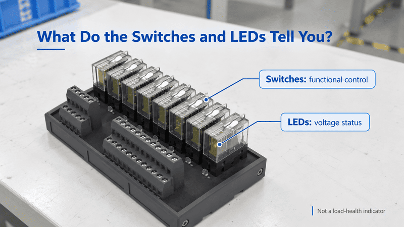
The red indicator shows input power, and each green indicator follows a switched output. The two rocker switches provide local functional control, but maintenance isolation still depends on the safety design of the complete machine.
| Front-panel element | What it normally indicates or controls | What it cannot prove |
|---|---|---|
| Red input LED | DC voltage is present at the monitored input point | Correct polarity at every output, adequate supply capacity, or healthy loads |
| Green channel LED | The related switched output is energized at the LED’s monitoring point | That the load is drawing current or operating correctly |
| Double-pole rocker switch | Opens or closes both conductors of one output in this design | Lockable safety isolation, absence of hazardous energy, or certified emergency stopping |
| Transparent fuse cover | Provides access to the replaceable common fuse | Individual branch protection or waterproof sealing |
When I review a cabinet design, I treat these rocker switches as operating controls, not automatically as safety disconnects. If maintenance requires verified isolation, the machine designer must specify an appropriate upstream disconnect, lockout method, stored-energy procedure, and voltage verification process.
A power supply converts voltage, a passive distribution block mainly multiplies connection points, a function-equipped distribution module adds features such as switches or protection, and a distribution box combines several components inside an enclosure.
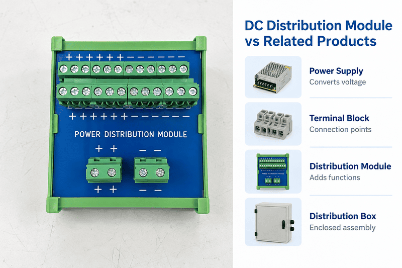
These products may appear in the same control cabinet, but they solve different parts of the power path. Correct product naming prevents a quotation from being based on the wrong function.
| Product | Converts AC to DC | Creates multiple outputs | Switching | Protection | Enclosure |
|---|---|---|---|---|---|
| AC-to-DC power supply | Yes | Sometimes limited terminals | Usually no branch switches | Internal source protection; branch protection varies | Product housing only |
| Passive distribution terminal block | No | Yes | No | No, unless a function version is selected | Normally installed inside a cabinet |
| Switched DC distribution module | No | Yes | Yes | Common or branch protection depends on design | Normally installed inside a cabinet |
| Fused DC distribution module | No | Yes | Optional | Common fuse, branch fuses, or both | Normally installed inside a cabinet |
| Electronic circuit-breaker module | No | Yes | Electronic channel control may be available | Monitored channel-level protection | Normally installed inside a cabinet |
| Complete DC distribution box | Not necessarily; may include a power supply | Yes | Optional | Depends on installed components | Yes, with a declared enclosure rating |
This is why a buyer asking for a “12 V power box” may actually need two products: a regulated 12 VDC power supply and a distribution module. Conversely, if a machine already has a suitable 24 VDC supply, adding another converter may be unnecessary; the requirement may simply be organized, protected branch distribution.
Check each output current, the simultaneous total current, the installed fuse, the upstream supply, conductor capacity, and load inrush. Passing only one of those checks is not enough.
The steady-state total is:
$$ I_{total}=I_1+I_2+cdots+I_n $$
For a two-channel module, both of these conditions must be satisfied:
$$ I1 leq I{channel max}, qquad I2 leq I{channel max} $$
and:
$$ I_1+I2 leq I{allowed shared current} $$
The “allowed shared current” is the lowest applicable limit in the assembled circuit. It may be set by the installed fuse, power supply, input connector, wiring, module rating, ambient derating, or another approved component—not simply the 20 A module-path number.
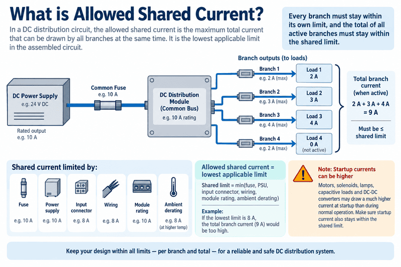
Every branch must remain within its own limit, and all simultaneous branches must remain within the shared limit. Motors, solenoids, lamps, capacitive loads, and DC-DC converters can also create startup current above their normal running value.
The following examples illustrate the selection logic. Replace the limits with the verified ratings of the actual module before applying them to a real installation:
| Load combination | Branch check | Shared-current check | Initial conclusion |
|---|---|---|---|
| Channel 1: 3 A; Channel 2: 4 A | Both below the verified branch limit | 7 A total is below the verified shared limit | Potentially suitable after checking inrush, wiring, temperature, and supply |
| Channel 1: 6 A; Channel 2: 6 A | Both below the verified branch limit | 12 A total exceeds the verified shared protection limit | Not suitable merely because each branch is below its individual limit |
| Channel 1: Above the verified branch limit; Channel 2: off | Branch limit exceeded | Total may still be below the shared limit | Not suitable because the branch limit is exceeded |
| Channel 1: 4 A motor; Channel 2: 3 A valve bank | Running currents appear acceptable | 7 A steady-state | Inrush and switching duty must be checked before approval |
For inductive or capacitive loads, the nameplate running current is only part of the answer. I ask for startup current, pulse duration, switching frequency, and whether both loads start together. A circuit that looks acceptable at steady state can still nuisance-blow a fuse, weld a switch contact, or pull the DC bus below the equipment’s operating threshold during startup.
A compact DC distribution module is useful where one existing low-voltage DC source must feed several nearby devices with organized wiring and convenient local control.
Typical applications include:
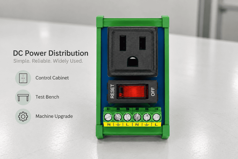
A rail-mounted module keeps short branch wiring organized inside a suitable cabinet. The cabinet—not the exposed module—provides the required environmental and touch protection for the installation.
The same module is not automatically suitable for every DC application. I would not select an open rail-mounted unit as a standalone outdoor product, a waterproof junction box, an AC-to-DC converter, a safety-rated isolator, or a substitute for selective branch protection. High fault-current battery systems also require careful coordination of fuses, conductors, connectors, and prospective short-circuit current.
Use conductors within the published terminal range, strip them to the specified length, preserve polarity, and verify the termination by inspection and a gentle pull test. Wire size must be selected for the circuit—not merely because it physically fits the terminal.
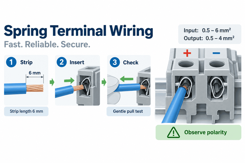
The reference terminal uses a 6 mm strip length. The input accepts the published 0.5–6 mm² range and the outputs 0.5–4 mm², but conductor ampacity, voltage drop, insulation, temperature, and protection must still be checked separately.
My normal wiring review follows this sequence:
For long cable runs, voltage drop can become the limiting factor before the terminal’s maximum conductor size is reached. The load must receive enough voltage under real operating current, including simultaneous loading and startup events.
Choose the module from the electrical architecture and fault behavior you need, not from channel count alone. Voltage, branch current, total current, protection topology, terminal interface, mounting, environment, and documentation all affect the final choice.
| Selection question | Information to confirm | Why it changes the product choice |
|---|---|---|
| What is the source? | Battery or regulated supply; nominal, minimum, and maximum voltage | Confirms voltage and polarity compatibility |
| How many loads are connected? | Required channel count plus reasonable expansion | Determines the number of branch outputs |
| What does each load consume? | Running current, startup current, pulse duration, and duty cycle | Determines switch, terminal, conductor, and protection ratings |
| What is the simultaneous total? | Which loads can operate or start together | Prevents overloading the common path and supply |
| What happens during one branch fault? | All outputs may stop, or healthy branches must remain live | Determines common fuse versus branch-selective protection |
| Is local switching needed? | No switch, single-pole switch, or both-conductor switching | Changes control and isolation behavior |
| What indication is required? | Input power, output state, blown-fuse indication, or diagnostic communication | Basic LEDs and diagnostic monitoring are not equivalent |
| How will wires connect? | Wire size, solid/stranded conductor, ferrules, spring or screw terminals | Ensures reliable, serviceable termination |
| Where will it mount? | TH35 DIN rail, G rail, panel, or custom assembly | Affects mechanical integration and usable cabinet space |
| What is the environment? | Temperature, vibration, contamination, moisture, altitude, and enclosure rating | An open module normally relies on the cabinet for protection |
| What approvals are required? | Complete-product certification, material recognition, machine or market requirements | A material’s UL 94 rating does not certify the complete device |
| What documentation is available? | Datasheet, dimension drawing, wiring diagram, certificates, and traceability | Allows the design team to validate rather than assume performance |
When I receive an inquiry, I do not start with “two channels or four channels?” I start with the source voltage, each load, and the required fault response. A two-channel common-fuse module is efficient when both circuits may shut down together. It is the wrong topology when one failed branch must not interrupt the other.
A useful quotation request should describe the complete DC circuit: source, loads, current, channel count, protection behavior, terminals, mounting, and operating environment.
| Information | Example format |
|---|---|
| Input source | 24 VDC regulated power supply |
| Source current capacity | 10 A continuous |
| Number of outputs | 2 channels |
| Load on channel 1 | Solenoid valve bank, 3 A running, 6 A inrush for 100 ms |
| Load on channel 2 | LED work light, 2.5 A running |
| Simultaneous operation | Both channels may start together |
| Protection requirement | Common fuse acceptable / individual branch isolation required |
| Switching requirement | Separate ON/OFF control; disconnect both conductors if available |
| Input connection | Spring terminal; state required wire size |
| Output connection | Spring terminal; state required wire size |
| Mounting | TH35 DIN rail |
| Indicators | Input power and individual output-state LEDs |
| Environment | Inside control cabinet, ambient temperature range provided |
| Required documents | Datasheet, dimension drawing, wiring diagram, and applicable certificates |
| Order requirement | Prototype quantity and estimated production volume |
At NITAI, this information helps us identify whether a compact switched module is appropriate or whether the project needs individual fuses, electronic circuit breakers, more channels, another terminal style, or a complete enclosed assembly.
No. A standard distribution module requires an existing DC input. Use a suitable AC-to-DC power supply upstream when the available source is AC.
Only when the exact module is rated for the selected voltage and every connected component is compatible. The voltage rating is model-specific, and the loads, LEDs, connectors, insulation, and protective devices must all suit the actual system voltage.
No. The reference topology has one replaceable common input fuse. The two channels have separate switches, but they do not have separate branch fuses.
Do not assume so. The allowed simultaneous load is governed by the verified branch rating, shared-path rating, installed protection, power supply, wiring, temperature, and load behavior of the complete circuit.
No. It indicates voltage at the monitored output state. A disconnected, failed, or incorrectly wired load may still leave the LED illuminated.
Not automatically. It is a convenient functional switch. Safety isolation requires an appropriately designed and documented isolation method for the complete equipment.
No. The exposed module does not become waterproof because its terminals have a cover. Install it inside an enclosure with the environmental and ingress-protection rating required by the application.
Not without a documented connector rating. The jack, mating plug, cable, and temperature rise must be separately verified. Do not transfer the terminal-input rating to a different connector by assumption.
Both channels lose power. Select a module with individual branch fuses or electronic circuit breakers if healthy branches must continue operating after another branch faults.
A DC power distribution module is a practical way to divide one existing DC source into organized output circuits, but correct selection depends on more than the number of outputs. The branch current, simultaneous total, inrush, fuse topology, wire range, switch function, mounting, enclosure, and required fault behavior must all be confirmed.
The two-channel spring-terminal design discussed here is well suited to compact systems where two loads need independent local switching and a shared fuse is acceptable. It should not be described as an AC-to-DC power supply, a waterproof box, or a module with individual branch protection.
If you are preparing a DC distribution project, contact NITAI with your input voltage, load currents, startup behavior, output-channel count, protection requirements, terminal preference, rail type, enclosure conditions, and documentation needs. We can then discuss whether a common-fuse switched module or another distribution architecture is the better fit.
An M12 male connector 5-pin B-coded may look like a straightforward line item, but its name does not…
5V relay modules are used to let a low-voltage controller switch a separate electrical circuit, but many buyers…
A relay module looks simple until a control cabinet fault appears after commissioning. One wrong assumption about COM,…
NITAI manufactures terminal blocks, M8/M12 waterproof connectors and industrial distribution modules for global OEMs, distributors and automation customers.
Leave a Reply