Oct 17, 2026
How Do I Choose the Right M8 8 Pin Female Connector for My Equipment?
An M8 8 pin female connector can look like the right replacement on a purchasing list and still…

If you've ever sent a supplier an inquiry for "PLC modules" and received a dozen clarifying questions back, you're not alone. The term covers everything from CPU cards to cabinet wiring blocks, and buying the wrong category doesn't just waste money — it stalls your entire system build.
The term "PLC modules" actually describes two distinct layers of a control system.1 The first layer includes PLC controller-native modules: CPU, power supply, digital I/O, analog I/O, communication, safety, and special-function cards that slot directly into a PLC rack. The second layer includes cabinet-level interface and wiring modules — PLC interface modules, relay modules, distribution modules, and terminal blocks — that connect field devices to the PLC without being PLC-brand hardware.
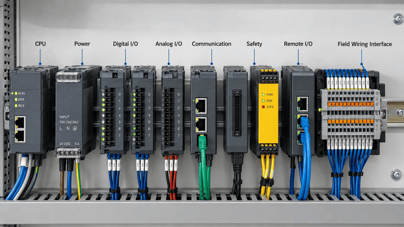
Understanding which layer you're working in changes every part of the purchasing decision — signal type, voltage range, isolation requirement, installation method, and connector format all depend on it. The sections below walk through each module type, what problem it solves, and what specifications actually matter when you're evaluating a supplier or preparing a wiring inquiry.
Most procurement problems start before anyone opens a catalog. When a buyer asks for "PLC modules," the supplier doesn't know which layer they mean — and the buyer sometimes doesn't either.
In my experience handling wiring-related inquiries and reviewing control cabinet drawings, the term "PLC module" appears in at least three different contexts: PLC rack expansion hardware, signal interface components inside the cabinet, and generic wiring accessories someone has grouped under the same label. Each context leads to a completely different product and supplier.
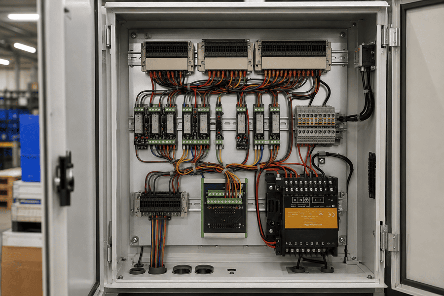
Before reviewing any product specification, it helps to decide which layer you are actually purchasing for.
Layer 1 — PLC controller modules (rack-native): These are manufactured or approved by the PLC brand — Siemens, Mitsubishi, Allen-Bradley, Omron, Schneider, and others. They mount directly into the PLC rack or chassis. They are not interchangeable across brands.2 Selection follows the PLC platform's own catalog and programming environment.
Layer 2 — Cabinet interface and wiring modules (brand-independent): These live inside the control cabinet but are not part of the PLC rack. They include:
Layer 2 products are sourced independently from the PLC brand. They follow IEC standards, DIN rail mounting conventions, and connector specifications — not PLC manufacturer catalogs.3
Key takeaway: If your question is "which CPU or I/O card do I add to my PLC rack," that is a Layer 1 question. If your question is "how do I connect 32 sensors cleanly to my PLC terminal rows," that is a Layer 2 question. They need different suppliers, different specs, and different inquiry formats.
Rack-native PLC modules handle the core logic, power, and signal processing of the PLC system itself. Choosing the wrong type here breaks the entire control program, not just the wiring.
These modules plug into the PLC's backplane or rack and communicate over the PLC's internal bus.4 They are sold and supported by the PLC manufacturer or authorized distributors. An equipment builder selecting these should always work from the PLC platform's own technical documentation.
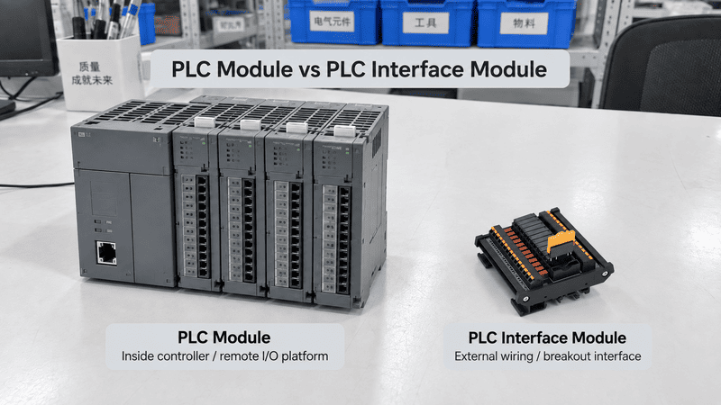
The CPU module executes the control program, manages I/O scanning, and handles communication with other devices.5 It defines the PLC's processing speed, memory capacity, number of supported I/O points, and network connectivity options.
Key selection factors for CPU modules include:
One important note: the CPU module determines which expansion modules are compatible. You cannot mix CPU and I/O modules across PLC brands, and in some cases, not even across product families within the same brand.
The power supply module converts incoming AC or DC supply voltage to the DC voltages the PLC rack needs internally. It also protects other rack modules from power fluctuations.
Buyers frequently underestimate power supply selection. The correct approach is to calculate the total current draw of all installed modules — including I/O cards, communication cards, and any future expansion — and add a safety margin, typically 20–30%.6
Common mistakes in power supply selection:
Digital input modules read on/off signals from field devices: push buttons, limit switches, proximity sensors, relay contacts, and similar discrete devices. Digital output modules switch on/off signals to field devices: solenoid valves, indicator lights, motor starters, and relay coils.
Critical specifications to verify before purchasing any digital I/O module:
| Specification | Why It Matters |
|---|---|
| Input voltage range (e.g., 24VDC, 120VAC) | Must match the field device's signal voltage |
| Input current per channel | Affects sensor compatibility |
| Output type: relay, transistor (NPN/PNP), or triac | Determines load type and switching speed |
| Maximum load current per output channel | Must exceed the connected device's inrush and steady-state current |
| Isolation: optocoupler or transformer isolated | Protects PLC from field-side faults |
| Channel grouping and common arrangement | Affects wiring and grounding strategy |
| Protection: short-circuit, overload, reverse polarity | Affects system reliability |
I/O point count is only the starting point. I've seen inquiries where a buyer specified "32 DI, 16 DO" but hadn't confirmed whether the sensors were NPN or PNP, or whether the output loads were inductive. Those details change the module selection completely.
Analog input modules convert continuous physical signals — temperature, pressure, flow, position — into digital values the CPU can process. Analog output modules convert digital values back into continuous signals to drive actuators, variable frequency drives, and proportional valves.
Common analog signal types:
Resolution (typically 12-bit, 14-bit, or 16-bit) and sampling rate matter significantly in process control and measurement applications.7 Buyers should also verify whether the module provides channel-to-channel isolation, which is important when measuring signals from different grounding references.
Communication modules add network connectivity beyond what the CPU provides natively. Common industrial protocols supported include:
Each communication module requires configuration within the PLC programming environment. Hardware selection and software configuration must be treated together.
Safety modules — safety I/O, safety relays, and safety CPUs — are certified to functional safety standards such as IEC 61508 and IEC 62061, and achieve SIL (Safety Integrity Level) or PL (Performance Level) ratings as defined in ISO 13849.8
These are not interchangeable with standard I/O modules. Safety applications — emergency stop circuits, light curtains, two-hand controls, safety gates — require the certified hardware and the qualified engineering evaluation that standard modules cannot provide.
I always recommend that buyers working on machinery safety applications engage a certified functional safety engineer. Hardware selection alone is not sufficient; the entire safety function must be validated.
Special function modules handle tasks that require dedicated hardware processing faster than the CPU scan cycle can support9:
These are often overlooked in initial system design and added during commissioning as an afterthought. Identifying special function requirements early saves significant rework.
Cabinet interface and wiring modules are the layer most often confused with PLC rack modules in inquiries I receive. They are not manufactured by PLC brands, but they directly determine how cleanly, safely, and efficiently your PLC connects to the real world.
These components sit between the PLC's I/O terminals and the field wiring. Their purpose is to organize connections, adapt signal levels, isolate circuits, and distribute power or signals — tasks the PLC rack itself does not handle.
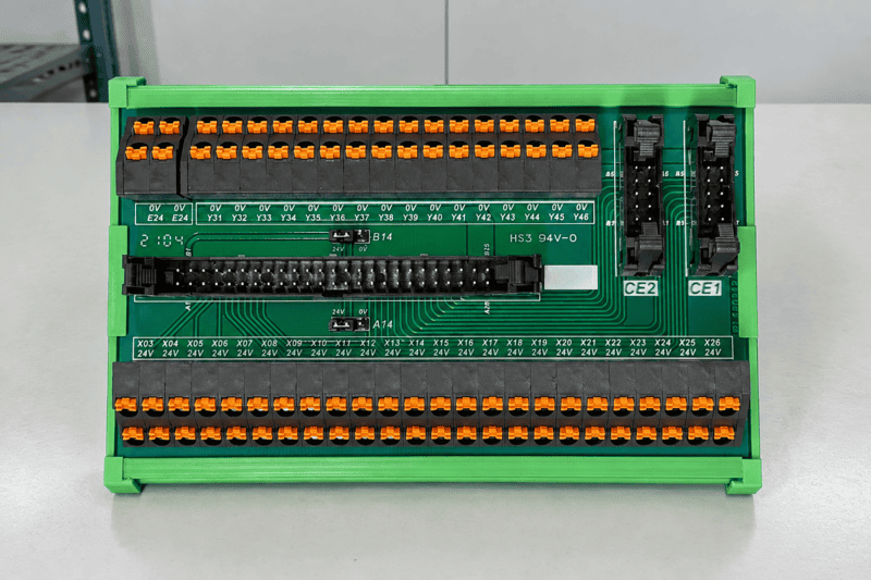
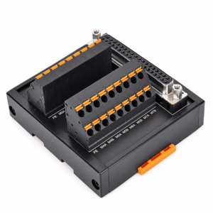
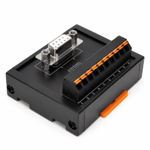
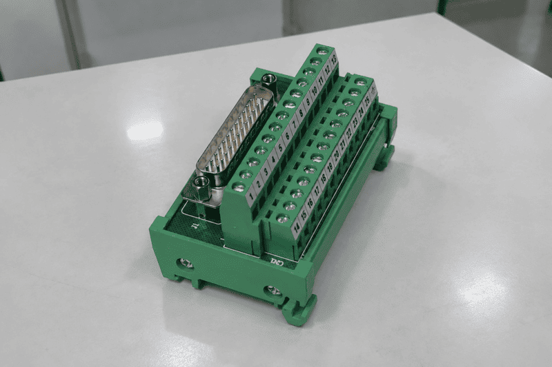
PLC interface modules — sometimes called I/O terminal modules, PLC wiring modules, or PLC breakout modules — convert the PLC's multi-pin or screw terminal I/O connector into organized, individually accessible terminals for field wiring.
The problem they solve:
Modern PLC I/O cards often use compact multi-pin connectors — 20-pin, 34-pin, 40-pin, 50-pin, and similar formats — to deliver high I/O density in a small rack footprint. Wiring field cables directly to these connectors is difficult, error-prone, and hard to maintain. PLC interface modules break out each pin to a labeled screw or spring-cage terminal, typically mounted on DIN rail inside the cabinet.
What to specify when evaluating PLC interface modules:
| Parameter | Explanation |
|---|---|
| Compatible PLC model and I/O card | The module must match the PLC's connector type and pin assignment exactly |
| Connector type and pin count | 20-pin, 34-pin, 40-pin, 50-pin, MIL connector, or proprietary |
| Terminal type | Screw terminal, spring-cage, or push-in |
| Terminal pitch | Affects cabinet space planning |
| Fusing or LED indication per channel | Some modules include per-channel fusing or status LEDs |
| DIN rail mounting | Standard 35mm DIN rail is most common10 |
| Current and voltage rating per terminal | Must accommodate the connected field device signals |
Many equipment builders I work with use PLC interface modules specifically to standardize wiring across multiple machines using the same PLC platform. It reduces wiring time, makes field troubleshooting faster, and eliminates direct-contact risk on dense connector faces.
Relay modules are signal conditioning components mounted on DIN rail inside the control cabinet. They contain one or more electromechanical or solid-state relays, each driven by a low-voltage control signal from the PLC output and switching an independent load circuit.
Why relay modules are used alongside PLC I/O:
PLC transistor outputs are typically rated for 0.5A or less.11 Many field devices — solenoid valves, motor contactors, high-wattage indicators — need more current than the PLC output can supply directly. Relay modules provide the isolation and current capacity bridge between the PLC's logic signal and the field load.
Key selection parameters for relay modules:
A frequently overlooked issue is the suppression of inductive loads. When a relay contact switches an inductive load, the voltage spike on release can damage the relay contact or nearby electronics.12 Specifying modules with built-in flyback diodes or RC snubbers reduces this risk.
Distribution modules split a single input — typically a 24VDC power supply rail, or a sensor supply line — into multiple fused or unfused outputs for individual field circuits.
Where distribution modules fit in the cabinet:
In a typical PLC cabinet, the 24VDC sensor supply powers dozens of sensors, actuators, and I/O devices. Running individual cables from the power supply to each device creates a wiring tangle that is hard to document and harder to fault-find. Distribution modules consolidate all supply connections at one DIN rail component, with each output individually accessible and often individually fused.
Types of distribution modules:
Selection checklist:
Distribution modules are often specified as an afterthought in cabinet design, but getting them right early reduces field fault response time significantly.
Terminal blocks are the single most universal component in control cabinet wiring. They provide the connection points where field cable conductors are terminated, labeled, and made accessible for testing and maintenance.
Common terminal block types and their applications:
| Type | Application |
|---|---|
| Standard feed-through terminal | General-purpose wire-to-wire connection |
| Ground terminal | PE (protective earth) connections |
| Fused terminal | Individual circuit protection at the terminal point |
| Disconnect terminal | Circuit isolation for testing and maintenance |
| Double-level / triple-level terminal | Space-saving multi-circuit connections |
| Spring-cage terminal | Vibration-resistant, tool-free wire insertion |
| Push-in terminal | Fast installation for fine-stranded wire |
| Sensor / actuator terminal (M8/M12) | Direct field device connection without intermediate wiring |
Critical terminal block specifications:
Terminal blocks look simple, but I regularly see issues in cabinet drawings where the specified terminal cross-section doesn't match the actual cable size, or where the rated voltage is borderline for the application. These details matter for both safety and certification.
Knowing the module categories is only the beginning. The selection risk I see most often is buyers specifying modules by quantity — "I need 32 inputs and 16 outputs" — without connecting that count to the actual signals, voltages, and installation requirements of the application.
A better approach is to build your selection around a set of questions for each signal in the system.
"PLC Control Cabinet Wiring Methods and Best Practices", https://industrialmonitordirect.com/blogs/knowledgebase/plc-control-cabinet-wiring-methods-terminal-blocks-and-layout?srsltid=AU7gw4Wo2AArq3XDJFmde7WlZiDHWl8gQI9kx_8YHqshhUKm-lMHHwfP. An engineering reference on PLC system architecture distinguishes processor, power, communication, and I/O modules from the external terminal and wiring components used to connect field devices, supporting the article's two-layer purchasing distinction; the source may not use the exact phrase “two layers.” Evidence role: general_support; source type: education. Supports: A neutral automation or engineering source should support that PLC systems include rack/controller modules and separate field-wiring or cabinet interconnection components.. Scope note: Contextual support for the article's classification rather than direct proof of the wording. ↩
"Programmable logic controller", https://en.wikipedia.org/wiki/Programmable_logic_controller. PLC architecture references describe modular PLC hardware as using controller-family-specific racks, backplanes, and expansion modules, supporting the statement that rack-native modules are not generally interchangeable across brands. Evidence role: general_support; source type: education. Supports: A PLC textbook, university course note, or neutral automation reference should explain that PLC modules are designed for particular controller families, racks, or backplanes.. ↩
"DIN Rail Standard Explained: IEC 60715, TS35 & TS15 Guide", https://payapress.com/din-rail-standard/. IEC and related technical references define standardized mounting rails and terminal-marking conventions for electrical equipment, supporting the article's claim that cabinet wiring components are commonly specified by standards and mounting formats rather than by a PLC platform catalog. Evidence role: general_support; source type: institution. Supports: A standards body or technical reference should support that DIN rail mounting and IEC terminal/connector standards are widely used for industrial control cabinet components.. Scope note: This supports the standards-based context for cabinet components, not every possible interface module on the market. ↩
"PLC Hardware - PLC Backplane & Other PLC Components", https://library.automationdirect.com/plc-hardware/. PLC architecture materials describe modular controllers as using a rack or backplane bus through which the CPU and I/O modules exchange data, supporting the article's description of rack-native module communication. Evidence role: mechanism; source type: education. Supports: A PLC architecture reference should explain how modular PLC racks use backplanes or internal buses to connect CPU, power, and I/O modules.. ↩
"PLC Basics and Scan Cycle Operations in Electrical ...", https://quizlet.com/study-guides/plc-basics-and-scan-cycle-operations-in-electrical-engineeri-ff3c3879-51d8-4ff7-b0d9-e4ecd5a08d74. Introductory PLC references define the processor or CPU as the component that executes the user program, performs the input/output scan, and coordinates communications, supporting the article's description of CPU module functions. Evidence role: definition; source type: education. Supports: A neutral PLC reference should define the CPU's role in program execution, I/O scanning, and communications.. ↩
"Power Supply Sizing for Industrial Control Panels", https://industrialmonitordirect.com/blogs/knowledgebase/power-supply-sizing-for-industrial-control-panels?srsltid=AU7gw4XoQS974hSyjIfhUJOCEiyqgrzMkS5FV5SdSboaD6Y8Mc8MsDWu. Control-panel power-supply sizing guidance commonly recommends allowing additional capacity above calculated load to account for inrush, tolerance, and future expansion, supporting the article's 20–30% headroom statement as an engineering rule of thumb. Evidence role: general_support; source type: education. Supports: A control panel design guide, university note, or neutral engineering reference should support the practice of adding power-supply capacity margin above calculated load.. Scope note: The exact percentage may vary by code, manufacturer, duty cycle, ambient temperature, and expansion policy. ↩
"Chapter 14: ADC, Data Acquisition and Control", https://users.ece.utexas.edu/~valvano/Volume1/E-Book/C14_ADCdataAcquisition.htm. Measurement and data-acquisition references explain that converter resolution determines quantization granularity while sampling rate constrains how changing signals are captured, supporting the article's statement that these specifications matter in analog PLC measurement and control. Evidence role: mechanism; source type: research. Supports: A measurement or data-acquisition reference should explain that ADC resolution affects quantization and that sampling rate affects dynamic signal capture.. ↩
"IEC 61508", https://en.wikipedia.org/wiki/IEC_61508. Functional-safety standards references identify IEC 61508 and IEC 62061 as standards using Safety Integrity Level concepts and ISO 13849 as the machinery-safety standard using Performance Level categories, supporting the article's statement about certification frameworks for safety modules. Evidence role: expert_consensus; source type: institution. Supports: Standards-body or institutional sources should confirm the relationship between IEC 61508, IEC 62061, ISO 13849, SIL, and PL in functional safety.. ↩
"What is PLC Scanning? Complete Guide to Scan Cycle", https://industrialmonitordirect.com/blogs/knowledgebase/understanding-plc-scan-cycle-complete-technical-guide?srsltid=AU7gw4XQLAnFmQLVfbrmJhzjp4aZqrAivHwc8laL9K_Jei2HoNWjBRVA. PLC training references explain that high-speed counter and motion modules process fast signals independently of the ordinary program scan, supporting the article's claim that some functions require hardware faster than the CPU scan cycle. Evidence role: mechanism; source type: education. Supports: A PLC education source should explain that normal scan-cycle execution can miss fast pulses or be unsuitable for time-critical motion/counting tasks, requiring special hardware modules.. ↩
"DIN rail", https://en.wikipedia.org/wiki/DIN_rail. DIN rail standards such as EN/IEC 60715 define 35 mm mounting rails widely used for industrial control equipment, supporting the article's statement that 35 mm DIN rail is the common cabinet mounting format. Evidence role: definition; source type: institution. Supports: A standards reference should identify 35 mm top-hat rail dimensions under DIN/EN/IEC rail standards.. ↩
"Choosing PLC Output Modules: Relay vs Transistor ...", https://industrialmonitordirect.com/blogs/knowledgebase/relay-vs-transistor-output-modules-selection-guide-for-plcs?srsltid=AU7gw4W0Nma981pyR3lY7YoG-vi6rxI66YVbODr-uU3Qtdp14kh1v5R7. PLC output-module references describe transistor outputs as low-current solid-state outputs and commonly show per-channel ratings in the sub-ampere range, supporting the article's explanation for using relay modules with higher-current field loads. Evidence role: general_support; source type: education. Supports: A PLC output-module reference should support that transistor outputs are intended for relatively low-current loads and often require interposing relays for larger loads.. Scope note: The exact 0.5 A threshold varies by PLC family, output grouping, ambient temperature, and module derating rules. ↩
"An inductive load such as a relay coil stores energy while ...", https://www.facebook.com/ElectronicsResearchDevelopment/posts/an-inductive-load-such-as-a-relay-coil-stores-energy-while-current-flows-through/1470788365065184/. Electrical engineering references on relay protection explain that interrupting current through an inductive load can produce a high-voltage transient and contact arcing, supporting the article's statement that suppression components reduce the risk of relay or electronics damage. Evidence role: mechanism; source type: education. Supports: An electrical engineering source should explain inductive kickback, contact arcing, and the role of flyback diodes or RC snubbers.. ↩
An M8 8 pin female connector can look like the right replacement on a purchasing list and still…
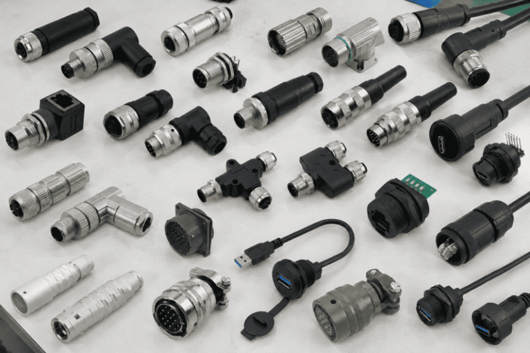
Connector types can look interchangeable in a catalog, but a familiar shape does not tell me whether two…
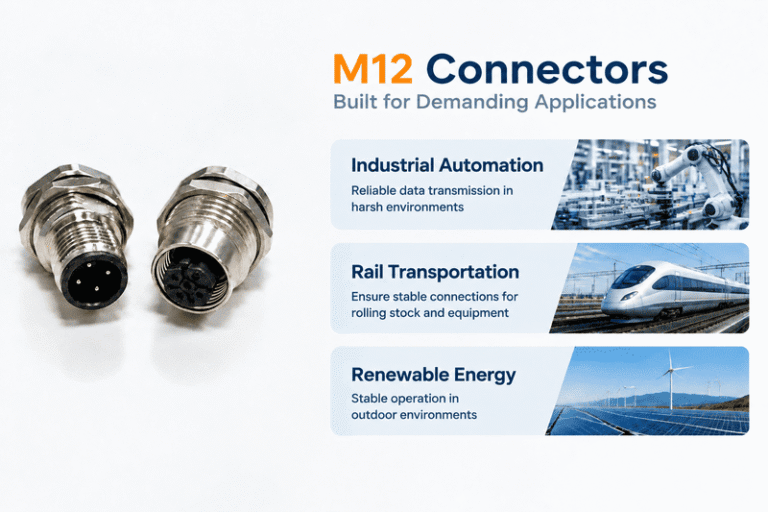
A coded and B coded M12 connectors can look similar in a purchasing list, but choosing the wrong…
NITAI manufactures terminal blocks, M8/M12 waterproof connectors and industrial distribution modules for global OEMs, distributors and automation customers.
Leave a Reply