Oct 21, 2026
What Is the Difference Between a Control Module and a Relay Module?
A control module and relay module can look like similar purchases when both appear on a control-panel parts…

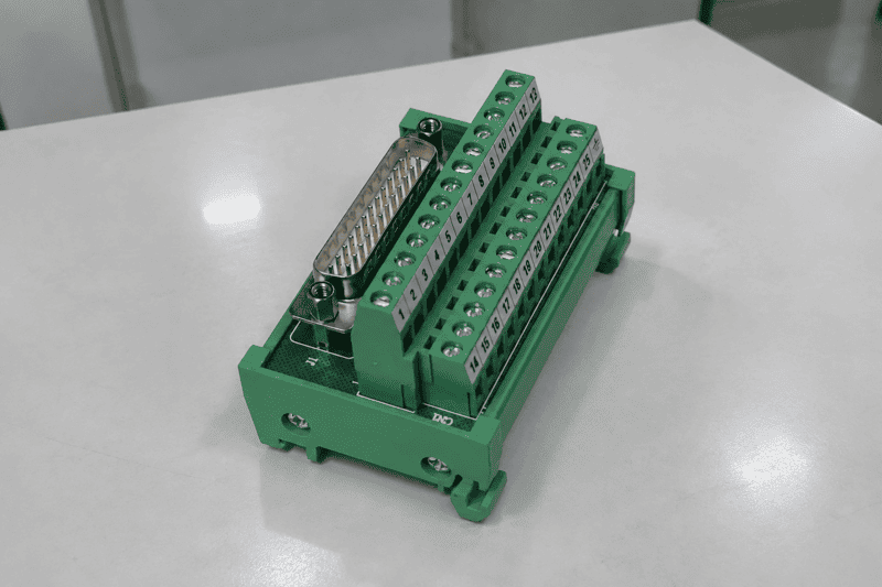
An industrial relay module can simplify PLC control-panel wiring, but a familiar input voltage or current marking does not establish that it suits an application. A mismatch can affect the PLC output, shorten contact life, or cause unreliable switching. I start selection by checking the controller side and the switched-load side separately.
An industrial relay module is a control-panel interface between a PLC or controller output and a field circuit. To choose one, I verify how the PLC drives the module, then check whether the module’s contacts are specified for the actual load. I also confirm the wiring diagram, protection features, dimensions, and supplier documentation before recommending a candidate for engineering review.
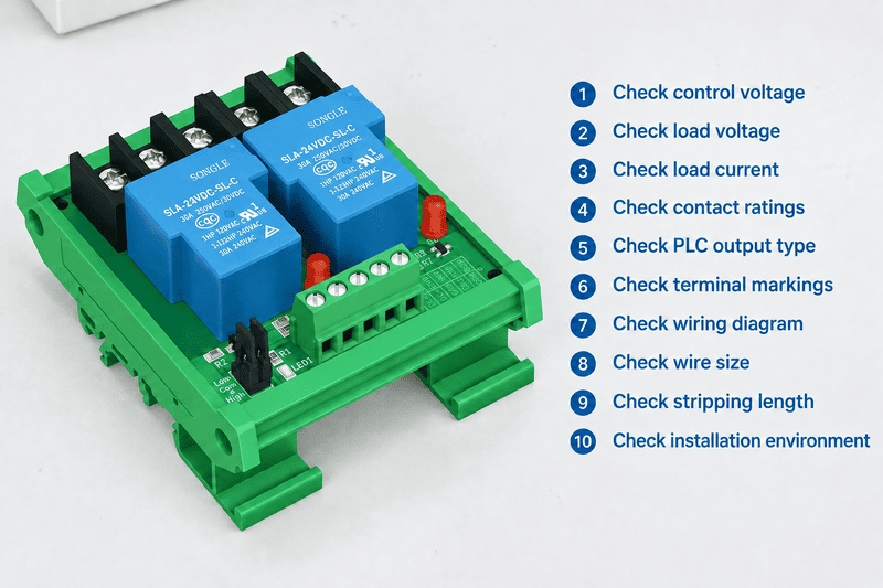
In selection inquiries, I often receive a short request such as “24 VDC input, 5 A output, eight channels.” That information helps narrow a search, but it leaves important questions open. The two checklists below show what I ask next and why those answers matter.
A PLC output needs a clear path to the equipment it controls. When a panel contains many field circuits, wiring and identification become harder to manage. An industrial relay module provides an organized interface, but its exact electrical behavior depends on the model and its circuit design.
An industrial relay module accepts a control signal from a PLC or controller and switches a separate field circuit through relay contacts.1 Its practical value can include orderly wiring, identifiable channels, and easier replacement. It can also prevent an unsuitable load from being connected directly to a PLC output, provided the selected module is compatible with both circuits.
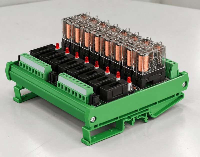
I do not treat a panel relay module as merely a general-purpose relay in a housing. A module may combine one or more relays with input circuitry, terminal connections, indicators, mounting hardware, and other model-specific components. Those details affect how a panel builder wires, tests, labels, and services the assembly.
The control side receives the signal that operates a channel. The load side contains the contacts that switch a field circuit. Those sides serve different purposes, so I check them against different specifications. In particular, a 24 VDC input tells us how the module is controlled; it does not tell us what load the output can safely switch.
For a panel maker, the module’s physical arrangement matters alongside its electrical ratings. I ask for the available mounting method, panel space, wire sizes, and preferred terminal style. I also check how channels and terminals are identified. Clear identification can help technicians trace a circuit and replace a component, although service procedures still depend on the panel design.
I also ask whether the buyer needs a replaceable relay, a complete replaceable module, or neither. A drawing or product photo alone may not answer that question. The manufacturer’s datasheet and ordering information should identify what can be replaced and which part numbers apply.
I use the module as an interface in the selection discussion. I do not assume that its presence makes a PLC output, field circuit, or completed panel suitable for use.
A “24 VDC PLC” description often leaves out the details that determine whether an output can operate a module input. I have handled inquiries where the voltage was the only control-side information supplied. Before I narrow the options, I ask how the specific output card sources or sinks current.
I check the PLC model, output-card model, output type, and channel specifications against the relay module’s input circuit. I also confirm the voltage range, required input current, common-terminal arrangement, and any off-state behavior. The module’s wiring diagram must show a valid current path for the proposed connection.
| Information I request | What I need to establish |
|---|---|
| PLC and output-card model numbers | Which output specifications and wiring diagrams apply |
| Output type and voltage range | How the card drives the proposed module input |
| Per-channel output current | Whether the output can supply the required input current |
| Common-terminal grouping | How channels share supply or return connections |
| Off-state leakage | Whether leakage could affect the module input |
| Diagnostic test pulses | Whether brief pulses could produce unwanted behavior |
| Module input circuit diagram | The intended current path, polarity, and terminal connections |
I check the output card’s per-channel rating rather than relying only on a card-level figure. I also review any group limits stated in the PLC documentation. If several module inputs share a PLC common, I ask the panel designer to account for that wiring arrangement.
A label such as “PNP compatible” or “NPN compatible” needs a model-specific check.2 Buyers and suppliers do not always use those terms with the same wiring assumptions. I compare the PLC output diagram with the module input diagram and identify where current flows when the output turns on. If the drawings do not make that path clear, I ask for clarification before suggesting a part.
Off-state behavior deserves attention too. Some output cards have leakage current or diagnostic pulses. I cannot infer from a nominal voltage whether a particular relay-module input will ignore them. I ask for the relevant PLC specifications and the module’s input characteristics, then leave the final behavior assessment to the qualified panel engineer.
When a customer sends only the PLC family name, I ask for the exact output-card part number. That small follow-up often determines which datasheet pages and terminal diagrams we need. It also keeps an initial product suggestion from being mistaken for verified PLC compatibility.
A module may respond correctly to a PLC output and still be unsuitable for the field load. A headline contact-current marking cannot describe every switching condition. I therefore ask what the contacts will switch, how often they will switch it, and what happens when that load starts or stops.
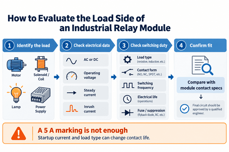
I verify the load’s AC or DC supply, operating voltage, steady current, inrush current, and load type against the module’s contact specifications. I also check contact configuration, common connections, switching frequency, expected electrical life, and any required fuse or suppression. An application-specific engineer should confirm the final circuit design.
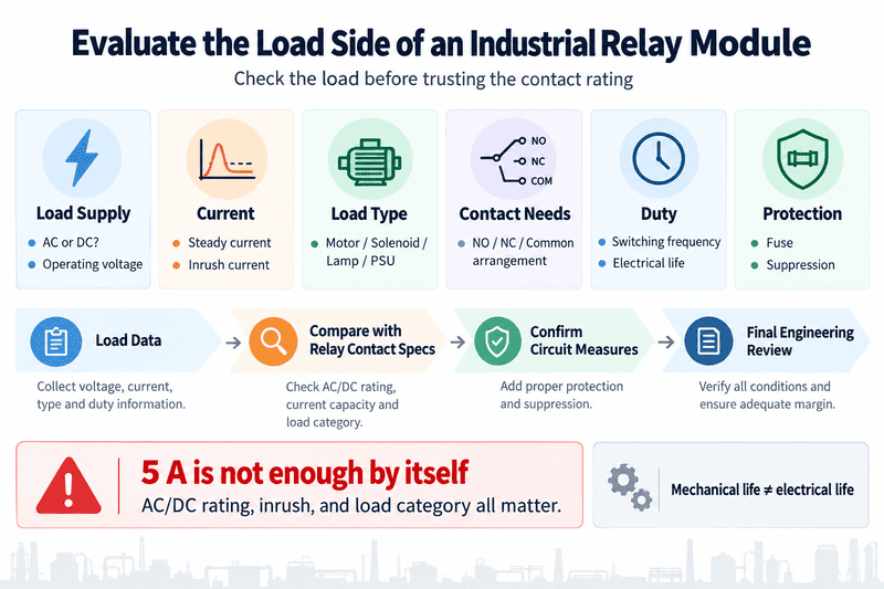
A “5 A” marking is not a blanket guarantee for every load drawing less than 5 A in normal operation.3 A motor, solenoid, contactor coil, lamp, or power-supply input may draw a higher current when switched.4 The contact rating and expected life may also differ between AC and DC applications and between load categories.5
When I receive a load description, I ask for the actual equipment or load datasheet where possible. A nameplate’s running current is useful, but it may not describe startup demand. If the buyer cannot provide inrush data, I flag that gap. I do not turn an incomplete load description into a confident contact-life claim.
The contact arrangement can rule out a module even when its electrical ratings appear suitable. For example, a design that needs separate supply connections for several loads cannot assume every multichannel module provides independent commons. I check the terminal diagram before proposing a channel count.
I also distinguish mechanical life from electrical life when reviewing documents. A mechanical-life figure does not establish how long contacts will last while switching a particular load.6 For a demanding or frequent switching duty, I ask a qualified electrical engineer to assess the published ratings, load behavior, and circuit measures together.
Product listings often mention indicators, protection, or isolation in a few words. Those terms can hide important differences in how a circuit is built and wired. I treat each feature as a question about the exact part number, not as a standard property of every industrial relay module.
I confirm status indication, surge suppression, polarity protection, electrical isolation, short-circuit protection, and PNP/NPN compatibility using the model’s datasheet and circuit diagram. I also check whether a stated feature applies to the input, the contacts, or another part of the assembly. A feature name alone does not establish its scope.
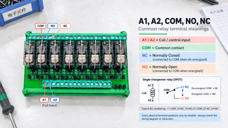
An indicator may show an input command, a relay state, or another condition, depending on the design.7 I do not assume that an illuminated LED proves the field load has power or that a contact has closed. The circuit diagram should show what drives the indicator.
Suppression also needs a precise description.8 A component across a relay coil serves a different location in the circuit from a measure fitted at a field load. The selected arrangement can affect switching behavior, so I ask the panel designer to review the complete circuit and the manufacturer’s instructions.
Likewise, I do not assume that polarity protection or short-circuit protection exists because a module is intended for industrial use. I look for an explicit specification and its limits. If a listing says “isolation,” I ask which circuits are separated and which published values apply. I do not translate a broad product description into an application-level safety conclusion.
For multichannel products, I also check what the diagram shows about shared inputs, commons, and contact terminals. A compact layout can save panel space, but it does not tell me whether channels are independent in the way a particular design requires.
My practical document request is short: the exact ordering code, current datasheet, circuit diagram, and terminal layout. Those documents give the buyer and engineer a common reference. If a feature is not documented clearly, I mark it as unconfirmed rather than filling the gap with an assumption.
A technically plausible module can still be difficult to purchase or build into a repeatable panel if the documentation, samples, or ordering details are unclear. I assess the supplier after I establish the electrical questions. That order keeps price or channel count from driving a premature choice.
I compare suppliers by asking for part-specific drawings, applicable specifications, sample availability, ordering codes, lead times, and change-control details. I ask buyers to verify any required certification documents for the exact product and market. I treat supplier information as input to their evaluation, not as engineering approval.
A consistent request makes supplier responses easier to compare. I suggest that panel makers send each supplier the same control-side and load-side information, while keeping confidential project details out of the initial inquiry where necessary.
| Request item | Why I ask for it |
|---|---|
| Exact module ordering code | To tie specifications and quotations to one configuration |
| Current datasheet and circuit diagram | To check ratings, input wiring, contacts, and features |
| Dimensions and 2D/3D/CAD files | To review panel layout and mounting |
| Terminal and wire specifications | To review the intended panel connections |
| Sample and production lead times | To plan evaluation and procurement |
| MOQ and customization scope | To compare purchasing and project options |
| Applicable certification documents | To verify the stated documents against the required market and part |
In my sales-support role at NITAI, I use this package to turn an initial inquiry into a clearer product discussion. NITAI manufactures industrial connectivity products and supports engineering documentation, sample development, OEM/ODM requests, and volume production. I describe those capabilities so buyers know what to request; I do not present them as evidence that an unreviewed module fits a particular circuit.
I ask buyers to check whether a quoted module matches the sampled module and whether drawings carry a revision or date. I also ask how the supplier handles substitutions or product changes during repeat orders. Those questions matter to panel builders who need consistent documentation across builds.
A sample can support a buyer’s evaluation, but it does not replace application-specific review. The responsible engineer should confirm the PLC connection, contact duty, protective measures, and complete panel requirements before the design is approved.
No. I read 24 VDC input as a control-side specification. I check the contacts separately for the load’s voltage, AC or DC type, steady and inrush current, and switching duty. The module’s datasheet must support the proposed load.
No. I use that figure only as a starting point because contact suitability depends on the published rating conditions and the actual load. I ask for the load type, operating voltage, startup behavior, and switching frequency before narrowing the options.
No. I check the exact PLC output card and the module’s input circuit diagram. The required current path, polarity, commons, leakage, and diagnostic pulses can affect compatibility. I do not infer PNP/NPN support from the nominal input voltage.
Not necessarily. I check what the specific LED monitors in the circuit diagram. An indicator may show a command or another internal state without confirming contact operation or voltage at the load. The panel’s test and diagnostic approach needs separate engineering review.
I ask for the PLC and output-card part numbers, control-side wiring details, load specifications, channel and contact requirements, switching frequency, and panel constraints. I also welcome drawings where available. A qualified engineer should verify any candidate against the full application.
I choose an industrial relay module by treating its PLC input and switched contacts as two separate checks. The exact output card and input circuit establish control-side suitability; the real load and duty establish contact-side suitability. I then verify model-specific features, drawings, and supplier documents before a qualified engineer reviews the application. For a NITAI product discussion, send your PLC details and load information through our contact page so we can identify the documents and samples relevant to your evaluation.
"(PDF) PLC intro", https://www.academia.edu/35384124/PLC_intro. Technical references describe interface relay modules as devices in which a control-side signal operates contacts that switch a separate circuit. Evidence role: definition; source type: education. Supports: A technical source defining an interface relay module and describing its control input and switched contacts.. Scope note: The internal circuitry and terminal arrangement vary by model and are not established by this general definition. ↩
"Certified Industry 4.0 Automation Specialist I Core Micro- ...", https://www.ncmich.edu/_binaries/_cce/c-200-certified-industry-40-automation-specialist-1-core-standards-10-22-1-2019.pdf. PLC wiring references distinguish sourcing and sinking outputs by the direction of current flow and the resulting input-circuit connection. Evidence role: mechanism; source type: education. Supports: A technical reference explaining sourcing and sinking outputs, polarity, and the current path needed for a compatible input circuit.. Scope note: The general distinction does not establish compatibility without the specific PLC and module circuit diagrams. ↩
"Utilization categories", https://en.wikipedia.org/wiki/Utilization_categories. Relay-rating literature treats contact current ratings as conditional on specified voltage, load type, and switching conditions. Evidence role: general_support; source type: paper. Supports: A technical source explaining that contact ratings depend on the specified switching conditions and load characteristics, not solely on a nominal current value.. Scope note: Rating categories and test conditions vary among standards and products; the cited source cannot replace the exact product specification. ↩
"Avoid Nuisance Tripping with Premium Efficiency Motors", https://www.energy.gov/sites/prod/files/2014/04/f15/avoid_nuisance_motorsys_ts6.pdf. Electrical engineering references describe transient inrush at energization for certain inductive, lighting, and power-electronic loads. Evidence role: mechanism; source type: research. Supports: Technical literature establishing that startup or energization current can exceed steady-state current in relevant load classes.. Scope note: Inrush magnitude and duration depend on the particular device and operating conditions and must be obtained from device-specific data. ↩
"Utilization categories", https://en.wikipedia.org/wiki/Utilization_categories. Studies of relay switching report that electrical contact life depends on the electrical duty and load characteristics. Evidence role: general_support; source type: paper. Supports: A technical source relating relay contact electrical life to switching voltage, current, AC or DC conditions, and load type.. Scope note: The relationship is product- and test-condition-specific, so general findings do not predict the life of a particular relay in an application. ↩
"Relay", https://en.wikipedia.org/wiki/Relay. Relay technical references distinguish mechanical endurance from electrical endurance measured while switching a defined load. Evidence role: definition; source type: paper. Supports: A technical reference distinguishing mechanical endurance without load from electrical endurance under specified switching conditions.. Scope note: Definitions and test conditions should be checked against the standard or datasheet applicable to the relay under review. ↩
"Relay Module Status - General Electronics", https://forum.arduino.cc/t/relay-module-status/450431. Circuit descriptions show that indicator lamps may be connected to different operating points, so their meaning depends on the device's circuit design. Evidence role: mechanism; source type: research. Supports: A technical source describing how indicator circuits can monitor different internal or external points and why indication must be interpreted from the circuit diagram.. Scope note: The precise condition represented by an indicator can only be confirmed from the specific module documentation. ↩
"PACKET 8 BOOKSTORE Relays 2009", http://users.etown.edu/w/wunderjt/PACKET%208%20BOOKSTORE%20Relays%202009.pdf. Engineering references distinguish coil suppression from suppression applied across a switched load and describe their different circuit functions. Evidence role: mechanism; source type: paper. Supports: A technical reference describing suppression methods for relay coils and switched inductive loads, including their locations and circuit effects.. Scope note: The appropriate suppression method and its effect depend on the circuit, component, and manufacturer's instructions. ↩
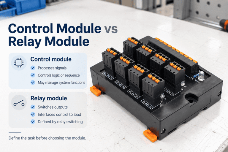
A control module and relay module can look like similar purchases when both appear on a control-panel parts…
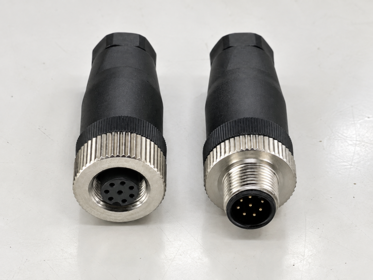
M12 connectors can carry different voltage ratings, so a buyer cannot choose one safely from the connector size…
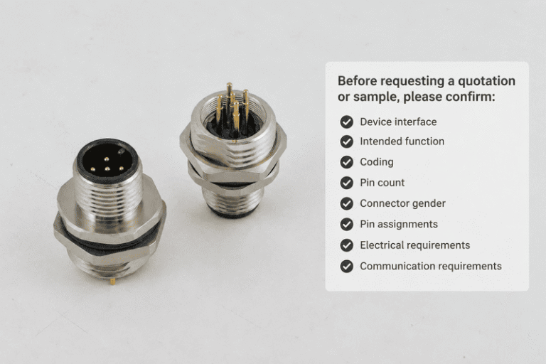
An M12 coding chart helps buyers distinguish connectors that look similar but serve different equipment functions. A wrong…
NITAI manufactures terminal blocks, M8/M12 waterproof connectors and industrial distribution modules for global OEMs, distributors and automation customers.
Leave a Reply