Sep 14, 2026
How Many Pins Are on an M12 Connector?
When someone asks for an M12 connector, the pin count is usually the first detail they mention. It…

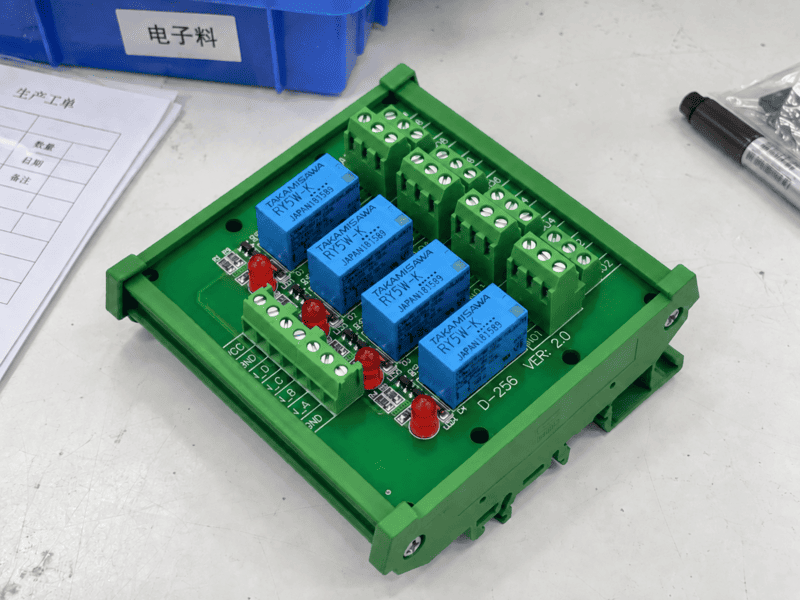
A relay module is a ready-to-wire switching interface that allows a low-power control signal to operate a separate load circuit. In an industrial control panel, it normally combines an electromechanical relay or solid-state switching element with input and output terminals, status indication, a mounting base, and sometimes protection components. The control side and the load side must be selected separately: a 24 VDC PLC signal may energize the module input, while the output contact switches a different AC or DC circuit within its specified rating.
When I receive an inquiry that only says “24 V relay module,” I do not choose a part from that description alone. I first separate the input voltage from the load voltage, then check the PLC output type, the real load, its inrush current, the required contact arrangement, and the switching frequency. Those details decide whether the module will work reliably.
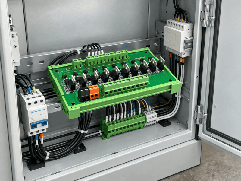
A relay module sits between the controller and the field circuit, but the two sides still require separate electrical checks.
| Quick Question | Short Answer |
|---|---|
| What does a relay module do? | It uses a control input to open or close a separate output circuit. |
| Is it the same as a bare relay? | No. A module normally adds terminals, mounting, indication, and optional protection. |
| Can it increase a PLC output's switching capability? | It can let the PLC command a separately rated contact circuit, but it does not amplify the signal in the analog sense. |
| Does every relay module provide the same isolation? | No. Insulation and isolation ratings are specific to the product design. |
| Can one module switch any 5 A load? | No. Voltage, AC/DC type, inrush, load category, temperature, and switching life all matter. |
A relay is the switching component itself; a relay module is an assembled product that makes that switching component easier to connect, mount, monitor, protect, and replace.
OMRON's technical overview of general-purpose relays describes a relay as a device whose contacts open and close in response to an input signal applied to a coil.1 That definition explains the core switching action, but an industrial electrician normally needs more than a loose component.
A bare relay may still require a socket, terminal connections, a retaining clip, an indicator, coil suppression, identification, and DIN-rail mounting. A relay module packages some or all of those functions into a usable interface. The exact package varies, so the word module alone does not confirm its circuit or ratings.
| Device | What It Usually Contains | Main Job | What It Does Not Automatically Guarantee |
|---|---|---|---|
| Bare electromechanical relay | Coil, armature, spring, and contacts | Mechanically switch one or more circuits | DIN-rail mounting, easy field wiring, indication, or protection |
| Relay with socket | Plug-in relay and terminal base | Make wiring and replacement easier | Correct PLC compatibility or correct load rating |
| Industrial relay module | Relay or SSR, terminals, PCB/base, mounting, and often an LED | Interface a controller with a field circuit | Universal isolation, universal polarity, or suitability for every load |
| PLC output module | Electronic or relay output channels controlled by PLC logic | Send control outputs from the PLC system | Direct switching of every external load |
| Contactor | Electromagnetic switching device designed for suitable power circuits | Switch higher-power loads such as motors or heaters | Direct compatibility with every PLC output |
| Safety relay or safety module | Safety-rated architecture with defined monitoring functions | Implement part of a validated safety function | Interchangeability with an ordinary interface relay |
This distinction prevents a common misunderstanding: a relay module is not simply a “stronger PLC signal.” The input circuit causes a defined change on the output side. The output then switches according to its own contact or semiconductor ratings.
Phoenix Contact's relay portfolio illustrates how electromechanical relays, solid-state relays, coupling relays, and complete modules can all sit within the same industrial product family.2 For selection, I therefore look at the circuit diagram and datasheet rather than relying on a category name.
A typical relay module contains an input interface, a switching element, output terminals, and a mechanical mounting structure; indication and protection are common options, not universal features.
A useful product image should identify the electrical and mechanical parts instead of showing only the housing.
| Component | Function | Question to Confirm Before Use |
|---|---|---|
| Input terminals | Receive the PLC, switch, or controller signal | What voltage, current, polarity, and PNP/NPN path are required? |
| Coil or electronic input | Converts the control signal into relay operation | Is it AC, DC, polarized, or non-polarized? |
| Electromechanical relay | Moves physical contacts | What are the contact form, load ratings, and expected electrical life? |
| Solid-state switching element | Switches the load electronically | Is the output for AC or DC, and what are its leakage and thermal limits? |
| COM/NO/NC output terminals | Connect the external load circuit | Which contact is required in the de-energized state? |
| LED indicator | Shows the state of the input circuit on many modules | Does the LED indicate only input voltage, or is another diagnostic available? |
| Suppression component | Limits a coil or switching transient | Is it a diode, TVS, RC network, or varistor, and how does it affect polarity or release time? |
| Socket or PCB | Carries the relay and internal connections | Is the relay replaceable or permanently mounted? |
| Screw, spring, or push-in terminal | Connects field conductors | What conductor type, cross-section, stripping length, and ferrule rules apply? |
| DIN-rail base or panel mount | Secures the module | What rail type, width, orientation, and spacing are required? |
Some slim modules also have a test button, mechanical position indicator, jumper channel, fuse, disconnect point, or pluggable relay. Multi-channel products may share a supply or common connection, while others keep every channel independent.
That is why two products with the same number of channels can behave differently. One may have eight isolated changeover contacts; another may have eight normally open outputs with a shared common. The terminal count and housing width do not reveal that difference by themselves.
An electromechanical relay module energizes a coil, creates a magnetic field, moves an armature, and changes the state of one or more physical contacts.
OMRON's relay operating-principle guide explains that current through the coil magnetizes the core, attracts the armature, and moves the contact; when the coil is de-energized, the return spring restores the normal state.1
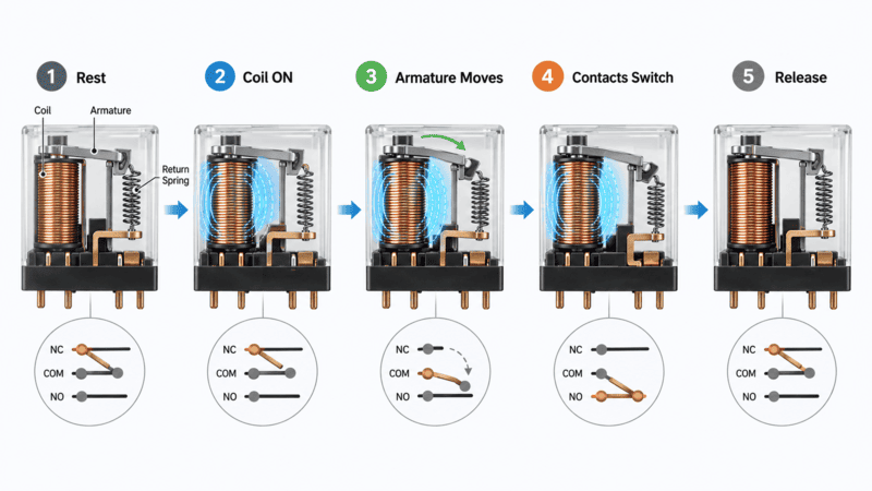
The input energizes the coil; the resulting mechanical movement changes the separate contact circuit.
| Stage | Input Side | Mechanical Action | Output Side |
|---|---|---|---|
| 1. Resting state | No coil voltage | Armature remains in its normal position | COM is connected according to the normal contact state |
| 2. Input applied | Current flows through the coil | Magnetic field builds | Contacts have not necessarily completed movement yet |
| 3. Operated state | Coil remains energized | Armature moves against the return spring | NO closes and NC opens on a typical changeover relay |
| 4. Input removed | Coil current stops | Magnetic field collapses | Contacts begin to return |
| 5. Released state | No coil voltage | Spring restores the armature | Original contact state is restored |
Mechanical movement introduces operating time, release time, contact bounce, sound, and wear. These are normal characteristics, not automatically faults. They do mean that switching frequency and required lifetime must be considered.
The coil and the contacts are different circuits. A 24 VDC coil does not mean the contact side is also 24 VDC, and a contact rated for a particular AC load does not tell us what voltage the PLC output must supply to the coil.
A solid-state relay module uses an electronic input and a semiconductor output instead of a mechanically moving contact.
OMRON's solid-state relay overview describes SSRs as contactless devices that use semiconductor switching elements; it also explains common optocoupler-based signal transfer between the input and output sections.3 Because there is no moving contact, an SSR can switch silently and frequently without mechanical contact wear.
That advantage comes with different limitations:
OMRON's SSR application guidance treats load current, inrush current, load type, ambient temperature, and mounting conditions as connected selection factors rather than one independent current number.4
| SSR Question | Why It Matters |
|---|---|
| Is the output AC or DC? | An AC triac output and a DC transistor/MOSFET output are not interchangeable. |
| What is the off-state leakage current? | A sensitive load may glow, chatter, or fail to turn fully off. |
| What is the on-state voltage drop? | It determines heat at the actual load current. |
| What is the switching frequency? | Frequent switching may favor an SSR, but it also affects thermal design. |
| What is the ambient temperature inside the cabinet? | Available load current may decrease as local temperature rises. |
| Is a heat sink required? | The answer depends on current, duty cycle, construction, and installation. |
A1 and A2 normally identify the coil or control-input terminals, while COM, NO, and NC identify the common, normally open, and normally closed contacts on the load side.
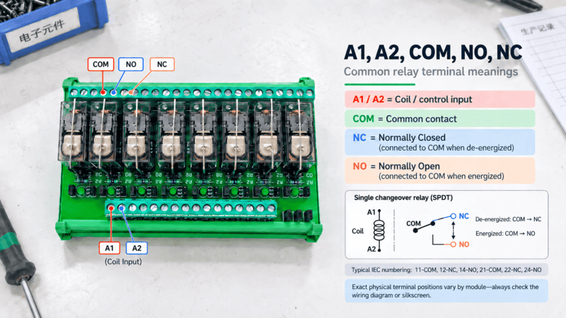
Terminal markings must always be checked against the exact module diagram; the layout shown here is conceptual.
OMRON's relay terminology defines NO contacts as open in the normal state and closed when operated, while NC contacts are closed in the normal state and open when operated.5 “Normal” means the relay is not energized unless the product documentation states another reference condition.
| Marking | Meaning | Typical De-energized State | Typical Energized State |
|---|---|---|---|
| A1 | One side of the coil or control input | Input not energized | Control voltage applied relative to A2 |
| A2 | Other side of the coil or control input | Input not energized | Return/reference path for the input |
| COM | Common moving contact | Connected to NC in a changeover circuit | Connected to NO in a changeover circuit |
| NO | Normally open contact | Open from COM | Closed to COM |
| NC | Normally closed contact | Closed to COM | Open from COM |
Choose the contact form from the required circuit behavior, not from the number of visible terminals.
| Common Description | Contact Behavior | Typical Use |
|---|---|---|
| SPST-NO / 1 Form A | One normally open path | Turn a load on when the relay energizes |
| SPST-NC / 1 Form B | One normally closed path | Open a circuit when the relay energizes |
| SPDT / 1 Form C | One common transfers between NC and NO | Select between two paths or provide changeover logic |
| DPDT / 2 Form C | Two changeover poles operated together | Switch two separate circuits with one coil |
Terminal numbers such as 11 = COM, 12 = NC, and 14 = NO are common on some industrial changeover relays. They are not a universal rule for every relay, every pole, or every manufacturer. I use the schematic printed on the actual module and then confirm it in the datasheet.
They may be. A plain DC coil can be non-polarized, but a module with a built-in LED, diode, or electronic input may require a defined polarity.
OMRON's general relay application guidance warns that built-in indicators and surge-absorbing diodes can create polarity requirements, and that the wrong coil supply type can cause malfunction or overheating.6
Before connecting A1 and A2, check:
A relay module provides a practical switching boundary between a PLC output and a field circuit, while also helping with contact conversion, organized wiring, status indication, and serviceability.
Industrial PLC interfaces can be passive wiring adapters or active modules that include relays, fuses, disconnect functions, or indication. Weidmüller's PLC interface overview shows how relay-isolated interfaces and integrated functions are used between PLC/DCS systems and field wiring.7
| Function in the Panel | What the Relay Module Can Provide | Boundary That Still Must Be Checked |
|---|---|---|
| Switch a separate field supply | PLC input command operates an independent contact circuit | Contact rating must match the real load |
| Convert output behavior | A transistor output can command NO, NC, or changeover contacts | The selected module fixes the available contact form |
| Separate circuits | Input and output may have defined insulation separation | Rated insulation, creepage, clearance, and test data are product-specific |
| Provide visible status | LED can show that the input circuit is energized | LED ON does not prove that the output contact or load is healthy |
| Simplify replacement | A plug-in relay can be changed without replacing all field wiring | Power must be isolated and the replacement must match |
| Organize many channels | Slim modules align PLC channels with field terminals | Shared commons, jumper limits, heat, and channel spacing still matter |
When I check a PLC relay-module application, I ask two separate questions:
The module must pass both checks. A matching voltage on one side does not prove compatibility on the other.
For a broader explanation of passive terminal interfaces, signal interfaces, relay interfaces, and distribution functions, see our PLC interface module guide. That article covers the larger interface family; this guide focuses specifically on relay switching.
A PNP output normally sources current to the relay-module input, while an NPN output normally sinks current from it; the input circuit and common connection must match that current path.
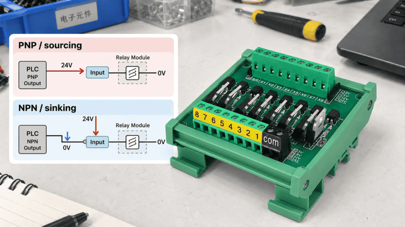
The same 24 VDC label can hide two different current paths, so the PLC output type must be identified.
| PLC Output Type | Simplified Current Path When ON | Typical Relay-Input Connection Concept | What to Verify |
|---|---|---|---|
| PNP / sourcing | PLC output supplies positive voltage to the load | Output channel to module positive input; module return to 0 V | PLC common arrangement, module polarity, and input current |
| NPN / sinking | PLC output provides a path toward 0 V | Positive supply to module input; other side through the PLC output | Input compatibility, common arrangement, leakage, and polarity |
| PLC relay output | PLC closes a dry or separately supplied contact | External supply drives the module input through the PLC contact | Contact rating, shared commons, and supply reference |
This table is only a circuit concept. PLC cards differ in common grouping, diagnostic circuitry, leakage current, protection, and allowable load. Relay modules also differ in whether the input is a coil, optocoupler, or electronic constant-current circuit.
I therefore ask for the complete PLC output-card number—not only the PLC brand—and the relay module input diagram. For a multi-channel module, I also total the input current and compare it with both the per-channel output limit and the PLC group's common-current limit.
Common industrial versions include plug-in electromechanical interfaces, solid-state relay modules, slim single-channel modules, multi-channel boards, latching relays, and modules designed for specialized monitoring or safety architectures.
| Relay Module Type | Main Strength | Main Limitation | Suitable Question to Ask |
|---|---|---|---|
| Plug-in electromechanical interface | Replaceable relay and visible mechanical switching | Contact wear and finite electrical life | Is easy field replacement important? |
| Slim DIN-rail relay module | Saves cabinet width and organizes channels | Thermal and load limits vary with construction | How much rail space and spacing are available? |
| Multi-channel relay module | Reduces repetitive wiring across several outputs | Commons, protection, and isolation may be shared | Are channels truly independent? |
| Solid-state relay module | Silent, fast, frequent switching | Leakage, voltage drop, heat, and AC/DC specificity | How often does the load switch? |
| Latching relay module | Maintains state without continuous coil power in the latched condition | Set/reset wiring and state behavior are different | Must state remain after the command is removed? |
| PCB relay board | Compact integration into OEM equipment | Service and field wiring may be less convenient | Is the module inside equipment or in a cabinet? |
| Force-guided contact module | Mechanically linked contacts can support defined feedback designs | Component alone is not a complete safety function | What standard and safety architecture apply? |
An ordinary interface relay must not be presented as a safety relay. Emergency-stop, guard-monitoring, and other safety functions require risk assessment, suitable certified devices, diagnostic coverage, correct wiring, and validation of the complete safety-related control system.
Choose an electromechanical relay when you need versatile dry-contact behavior and straightforward replacement; consider an SSR when the load requires frequent, fast, or silent switching and its leakage and thermal behavior are acceptable.
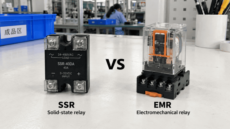
The correct choice depends on the load and duty cycle; neither technology is universally better.
| Selection Point | Electromechanical Relay Module | Solid-State Relay Module |
|---|---|---|
| Switching element | Physical contacts | Semiconductor device |
| Sound | Audible operation | Silent operation |
| Switching speed | Moderate | Fast |
| Frequent cycling | Limited by mechanical/electrical life | No mechanical contact wear, but heat still limits operation |
| Off-state current | Normally very low through an open contact | Leakage current may remain |
| On-state loss | Contact resistance | Semiconductor voltage drop and heat generation |
| AC/DC output flexibility | A contact may have separate AC and DC ratings | Output is normally dedicated to an AC or DC load type |
| Small-load behavior | Minimum switching load and contact material matter | Leakage can affect sensitive loads |
| Failure mechanisms | Wear, erosion, welding, spring/mechanical problems | Thermal or electrical semiconductor failure |
| Field replacement | Easy with some plug-in modules | Depends on module construction |
I do not replace an electromechanical relay with an SSR merely because “SSR life is longer.” If the load draws very little current, the SSR's leakage may prevent a clean OFF state. If the current is high, heat dissipation may dominate the design. If the circuit requires a true changeover dry contact, a standard two-terminal SSR output may not reproduce it.
Likewise, I do not choose an electromechanical relay merely because the current appears low. A rapidly cycled heater, lamp, or capacitive input can damage contacts long before a simple current comparison predicts.
Select the module in a fixed order: controller output, module input, load characteristics, output contact or semiconductor, switching duty, protection, mechanics, environment, and required compliance.
Identify the exact controller output before choosing the coil or input circuit.
I record:
A 24 VDC input module may draw only a small current, but eight or sixteen channels can still affect a grouped PLC output. Test pulses or leakage can also make a very sensitive electronic input flicker or operate unexpectedly.
Record the device type, not only its steady-state current.
| Load Data | Example of Useful Information | Why It Changes Selection |
|---|---|---|
| Load voltage | 24 VDC, 120 VAC, or 230 VAC | Sets output and insulation requirements |
| Normal current | Current after the device is operating | Used for continuous thermal and contact checks |
| Inrush/starting current | Peak value and duration from the datasheet | May weld contacts or exceed semiconductor surge limits |
| Load category | Resistive heater, solenoid, lamp, motor, contactor coil, capacitive input | Different loads create different turn-on and turn-off stress |
| Switching frequency | Operations per minute, hour, or day | Influences relay technology and expected life |
| Required lifetime | Expected operations or service interval | Allows comparison with electrical-life data |
| Fault protection | Fuse, breaker, electronic protection, or upstream limit | Protects conductors and the module under fault conditions |
Choose NO, NC, changeover, or multiple poles from the intended safe and normal circuit state.
Confirm:
Do not infer the channel count from the terminal count. A single changeover relay can use five or more terminals, while a multi-channel board may share supply terminals.
Switching frequency helps determine contact life, SSR heat, and the practical maintenance interval.
A relay that switches twice per shift has a very different duty from one controlling a heater every second. Mechanical life describes operation without the specified electrical load; electrical life applies under defined load conditions. The two values should not be confused.
Protection must address both the input coil transient and the load-side fault or switching transient.
Possible features include:
These are not interchangeable functions. A coil flyback diode does not replace a branch fuse, and a fuse does not eliminate contact arcing during normal switching.
Mechanical compatibility includes more than DIN-rail mounting.
| Installation Item | What to Confirm |
|---|---|
| Mounting | Rail type, orientation, locking method, and vibration conditions |
| Module width | Total channel density plus required spacing |
| Terminals | Screw, spring, push-in, pluggable, or connectorized interface |
| Conductors | Solid/stranded type, cross-section, ferrule, stripping length, and current |
| Jumpers | Pole count, current capacity, segmentation, and accidental cross-connection risk |
| Marking | Channel labels, circuit references, and service readability |
| Access | Probe points, relay replacement, fuse replacement, and wire release clearance |
Use the temperature around the installed module and verify the exact approvals required for the target machine and market.
Cabinet temperature can be higher than room temperature, particularly beside power supplies, contactors, or densely packed modules. Also confirm humidity, condensation, dust, corrosive atmosphere, altitude, vibration, pollution degree, overvoltage category, and required enclosure protection at the system level.
IEC 61810-1 covers general and safety requirements for electromechanical elementary relays used in electrical or electronic equipment.8 UL Solutions' explanation of IEC/UL 61810-1 describes the harmonized relay-standard framework and its relationship to earlier UL 508 treatment.9 These references help identify relevant requirements, but citing a standard does not mean a particular NITAI product is certified. Certification must be confirmed for the exact model and requested market.
Because the 5 A value applies only under stated test conditions; the actual voltage, AC/DC type, load category, inrush current, switching frequency, temperature, and required life can make a smaller nominal load more severe.
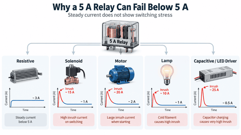
The steady-state current does not show the complete stress placed on a relay contact.
OMRON's terminology guide defines rated load as a specified combination of contact voltage and current, and separately defines maximum switching capacity, carry current, and inrush current.5 These numbers describe different limits; the largest printed current is not a universal working rating.
| Load Type | Main Switching Stress | Selection Evidence to Request |
|---|---|---|
| Resistive heater | Continuous current and heat | Rating at actual voltage, ambient temperature, and duty |
| Solenoid or contactor coil | Inductive turn-off voltage and repeated cycling | Inductive rating, coil energy, release requirement, and suppressor |
| Motor | Starting and possible stall current | Motor rating, start current, start duration, and switching life |
| Incandescent lamp | Cold-filament inrush | Lamp-load or permitted inrush rating |
| LED driver or switch-mode supply | Input-capacitor charging surge | Peak current, duration, and recommended switching device |
| Capacitive bank | Very high charging current | Pre-charge/current-limiting design and relay suitability |
| Transformer | Magnetizing inrush | Manufacturer guidance for transformer switching |
TE Connectivity's contact load and life paper explains that lamps, motors, solenoids, and capacitive loads can produce high initial or transient current and that contact life depends strongly on the load.10 Its examples are application guidance rather than universal multipliers, so I use the real load datasheet whenever possible.
A DC arc does not receive the natural zero crossing available in an AC waveform, so interruption can be more difficult at higher DC voltage or inductive load.
TE Connectivity's contact-arcing discussion connects arcing with contact erosion, material transfer, and possible welding.11 Contact gap, material, opening speed, voltage, current, polarity, and the external circuit all influence the result.
This is why I do not convert a relay's AC rating directly into a DC rating. I look for the manufacturer's DC switching table or load curve at the required voltage.
Do not assume that two contacts in parallel will share current equally or double the switching capacity.
Contact timing and resistance are never perfectly identical. One contact may make first, break last, and carry more of the switching stress. OMRON's general relay guidance specifically cautions against treating parallel contacts as a simple method for doubling capacity.6
Use a suppression method matched to the coil, supply type, required release time, and switching device; “add a diode” is not a universal answer.
When a DC coil is switched off, its magnetic energy creates a voltage transient. Suppression protects the PLC transistor or contact operating the coil and reduces electrical noise, but it can also change how quickly the relay or valve releases.
TE Connectivity's DC relay coil-suppression paper explains that suppression choice affects the transient as well as armature release dynamics and contact performance.12
| Suppression Method | Typical Application | Main Benefit | Important Trade-Off |
|---|---|---|---|
| Flyback diode | DC coil | Strongly clamps reverse voltage and is simple | Can slow current decay and delay release; polarity is critical |
| Diode plus Zener/TVS | DC coil | Allows a higher controlled clamp voltage | Component voltage/energy must be designed correctly |
| Bidirectional TVS | DC or polarity-variable transient paths where specified | Fast clamping without a single diode polarity | Leakage, clamp voltage, and energy rating must match |
| RC snubber | Often AC coils or contacts switching inductive loads | Limits voltage rise and arcing | Can pass leakage current and needs correct R/C sizing |
| Varistor/MOV | AC or DC transient limitation where specified | Absorbs higher-voltage transients | Clamp level, aging, and energy capability require evaluation |
There are two different locations to consider:
A module may already contain input suppression. Adding another device without reading the schematic can change polarity, release time, or diagnostic behavior. For a fast-acting valve, delayed release may be unacceptable even if the voltage spike is well controlled.
Wire the PLC output to the module input circuit, then use the module's separately rated output contact to complete the solenoid's load circuit.
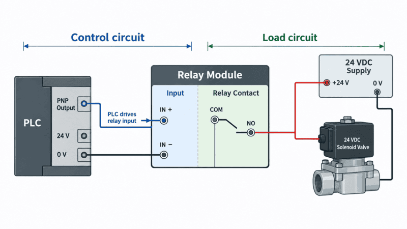
This is a conceptual architecture; the actual PLC, module, load, fuse, polarity, and terminal diagrams control the final wiring.
For a typical PNP output and a 24 VDC relay-module input, the control path may be:
The separate load path may be:
| Check Before Power-Up | Reason |
|---|---|
| PLC output type and common | Determines the control-side current path |
| A1/A2 voltage and polarity | Prevents non-operation or damage to an LED/diode input |
| Input current | Protects the PLC channel and common group |
| COM/NO/NC identification | Prevents reversed normal behavior |
| Load voltage and polarity | Protects the solenoid and output circuit |
| Normal and inrush current | Confirms relay contact suitability |
| Suppressor type and orientation | Controls transients without creating a polarity or timing error |
| Fuse or other branch protection | Protects conductors and equipment under faults |
| Separation and grounding | Maintains the intended circuit architecture |
For an NPN output, the input current path is reversed conceptually: the positive supply feeds the module input, and the PLC output sinks current toward 0 V. Do not reverse only two wires by habit; check the PLC diagram, module polarity, common grouping, and protective components.
This wiring example is educational. Mains-voltage and safety-related circuits must be designed and verified by a qualified person using the exact product documentation and applicable regulations.
The most common mistakes come from matching one visible specification while leaving the rest of the circuit undefined.
| Mistake | Why It Happens | Possible Result | Corrective Check |
|---|---|---|---|
| Saying only “24 V relay” | Input and load voltage are treated as one value | Wrong coil or wrong output circuit | State control voltage and load voltage separately |
| Selecting from “5 A” alone | Resistive rating is mistaken for a universal rating | Erosion, welding, overheating, or short life | Check voltage, AC/DC, load type, inrush, duty, and life |
| Ignoring PNP/NPN logic | Only nominal voltage is compared | Input never energizes or wiring creates a fault | Trace the complete current path |
| Assuming A1/A2 have no polarity | Internal LED or diode is overlooked | No operation or component damage | Read the module's input schematic |
| Copying 11/12/14 from another relay | Common numbering is assumed universal | COM, NO, and NC are miswired | Verify the exact model diagram |
| Treating LED ON as proof of output | LED monitors only the input on many modules | Faulty contact or missing load supply is overlooked | Measure the output state safely |
| Omitting inductive suppression | Coil energy is ignored | PLC damage, noise, arcing, or false signals | Select suppression for the actual coil and release time |
| Adding a diode to an AC coil | DC practice is copied to an AC circuit | Incorrect operation or component failure | Use an AC-compatible method specified by the manufacturer |
| Packing modules without a heat check | Room temperature is used instead of cabinet temperature | Thermal derating is exceeded | Check local ambient, spacing, and duty |
| Assuming all channels are isolated | Shared commons or PCB paths are missed | Unwanted coupling or unsafe wiring | Review the internal multi-channel schematic |
| Using a standard relay in a safety function | “Relay” and “safety relay” are confused | Required safety performance is not achieved | Use a validated safety architecture and suitable devices |
Troubleshoot the input, switching element, and load circuit separately instead of replacing the whole module immediately.
Before testing, isolate hazardous energy and use the correct measurement procedure. If the circuit contains mains voltage or forms part of a machine safety function, troubleshooting should be performed by qualified personnel.
| Symptom | Possible Cause | Practical Check |
|---|---|---|
| Input LED does not turn on | No PLC signal, wrong common, wrong polarity, wrong input voltage, open conductor | Measure the input at the module under the commanded condition |
| LED is on but no click | SSR design, failed coil/relay, insufficient input voltage, mechanical problem | Identify module type and verify input voltage against datasheet |
| Relay clicks but load stays off | Wrong contact, missing load supply, blown fuse, open wire, damaged contact | Trace COM-to-NO/NC and measure the load circuit safely |
| Load remains on after command is removed | Welded contact, wrong NC wiring, SSR leakage, external backfeed | Isolate circuits and test the output state without assuming failure mode |
| PLC output alarms | Input current too high, short circuit, incorrect common, suppression polarity error | Compare wiring and total current with PLC output specifications |
| Relay chatters | Unstable input voltage, PLC pulse behavior, loose terminal, control noise | Monitor input voltage and inspect terminations |
| Relay fails repeatedly | Inrush, arc energy, switching frequency, temperature, or suppression mismatch | Review real load waveform and electrical-life conditions |
| Sensitive load will not turn fully off | SSR leakage or snubber current | Measure off-state voltage/current and check load compatibility |
The LED is useful, but it normally answers only one question: “Is the module input receiving enough signal to turn the indicator on?” It does not confirm that the relay contact has not welded, that the fuse is intact, or that the external load supply exists.
Send the controller model, control input, actual load data, contact arrangement, channel count, circuit diagram, installation limits, and required approvals.
When I receive this information, I can review the application with our technical team without guessing from a product photograph.
| Information to Provide | Useful Example | Why We Need It |
|---|---|---|
| Application | PLC output switching eight solenoid valves | Establishes the circuit purpose |
| PLC/controller | Full manufacturer and output-card model | Confirms output technology and limits |
| Control input | 24 VDC, PNP/sourcing | Defines module-input compatibility |
| Load voltage | 24 VDC | Defines the output circuit |
| Load type | Solenoid coil | Identifies inductive switching stress |
| Normal current | Value from load datasheet | Supports continuous rating check |
| Inrush or coil data | Peak current, power, or coil datasheet | Supports switching and suppression review |
| Contact form | One NO contact per channel | Defines output terminals and normal state |
| Channel count | Eight independent channels | Defines module architecture |
| Switching frequency | Operations per minute or day | Supports life and technology selection |
| Protection | Input diode/LED, output fuse, load suppression | Defines internal and external protection |
| Terminals | Push-in; conductor size and ferrule requirement | Confirms wiring interface |
| Installation | 35 mm DIN rail, maximum overall width | Confirms mechanical fit |
| Environment | Cabinet temperature, vibration, humidity, altitude | Supports derating and material review |
| Compliance | Exact market approval or report required | Prevents an unsupported certification assumption |
| Customization | Pinout, connector, marking, PCB, housing, packaging | Defines what must differ from a standard module |
A photo is helpful for recognizing the housing and terminal arrangement, but it cannot reveal the contact material, internal diode, current path, insulation rating, or electrical-life data. For a replacement project, send the full side label, printed schematic, original model number, and load datasheet.
The short answers below cover the questions I most often need to clarify before a relay module can be selected or replaced correctly.
No. A relay is the switching component. A relay module normally adds terminals, a PCB or socket, indication, mounting, and optional protection around that component.
Not in the analog-amplifier sense. A low-power control circuit can command a separately supplied load circuit, but the output does not become a proportional, amplified copy of the input.
No universal isolation value should be assumed. Electromechanical relay coils and contacts are physically separate, and many SSRs use optical coupling, but rated insulation voltage, test voltage, creepage, clearance, and channel separation depend on the exact design.
Only if the module input is compatible with the PLC output. Check nominal voltage, operating range, input current, PNP/NPN path, polarity, common arrangement, leakage current, and group limits.
Some dry contacts have separate AC and DC ratings, but those ratings are not interchangeable. Use the specific table or curve for the actual voltage, load type, and switching duty.
The LED usually confirms the input state, not the complete output circuit. The wrong contact may be wired, the fuse may be open, the load supply may be absent, the contact may be damaged, or the field conductor may be disconnected.
No. SSRs suit frequent and silent switching, while electromechanical relays offer familiar dry-contact behavior and can be easily replaceable. Leakage, heat, output type, load, duty, and required contact arrangement determine the better option.
Do not assume so. Unequal contact timing and resistance can make one pole carry most of the switching stress. Use a device rated for the complete load or follow a manufacturer-approved circuit.
Do not assume it can. A safety function requires the appropriate safety architecture, certified components where required, diagnostics, wiring, and validation. An ordinary interface relay is not automatically a safety relay.
There is no single lifetime value for all applications. Mechanical life, electrical life, load type, voltage, inrush, switching frequency, suppression, temperature, and environment all affect service life. Compare the manufacturer's life data with the real circuit conditions.
Not automatically. The output circuit, leakage, voltage drop, heat dissipation, AC/DC compatibility, terminal functions, and failure behavior may differ even when the control voltage and housing look similar.
A relay module switches through mechanical contacts or a defined solid-state relay output; an optocoupler primarily transfers a signal optically between circuits. Some SSRs include optocouplers internally, but an optocoupler output is not automatically rated to switch the same field load as a relay module.
A relay module is a practical interface between a controller and a field circuit, but reliable selection requires separate checks of the input, output, load, duty, protection, installation, and compliance.
Before I recommend a standard or custom relay interface, I confirm:
If you are selecting a relay module for a PLC output, send NITAI the controller model, load datasheet, circuit diagram, number of channels, terminal preference, installation space, and required compliance. We can identify the confirmed requirements, point out missing electrical data, and review whether a standard layout or a custom module should be evaluated before quotation and sampling.
[OMRON Industrial Automation, “Overview of General Purpose Relays”](https://www.ia.omron.com/support/guide/36/introduction.html). Official technical guide explaining the basic relay definition, main relay categories, hinged-relay structure, and coil-to-contact operating sequence. It supports the general operating explanation in this article; individual ratings still come from the selected model's datasheet. ↩
[Phoenix Contact, “Relays and Solid-State Relays”](https://www.phoenixcontact.com/en-us/products/relays-and-optocouplers). Manufacturer product-family overview covering electromechanical relays, solid-state relays, coupling relays, and complete relay modules for industrial use. It supports the distinction between relay technologies and module formats, not a claim that every product contains the same features. ↩
[OMRON Industrial Automation, “Overview of Solid-state Relays”](https://www.ia.omron.com/support/guide/18/introduction.html). Official technical explanation of semiconductor switching, contactless operation, optocoupler-based construction examples, switching speed, contact wear, and heat generation. The internal circuit and isolation method must still be checked for each SSR. ↩
[OMRON Industrial Automation, “Further Information of Solid-state Relays”](https://www.ia.omron.com/support/guide/18/further_information.html). Official SSR application guidance addressing load types, load current, inrush current, operating conditions, and selection margin. Its examples do not replace the load and thermal curves for a specific module. ↩
[OMRON Industrial Automation, “Explanation of Terms for General Purpose Relays”](https://www.ia.omron.com/support/guide/36/explanation_of_terms.html). Official terminology reference for NO and NC contacts, contact forms, rated load, carry current, switching capacity, inrush current, electrical life, and related relay terms. Definitions are general; numeric limits are product-specific. ↩
[OMRON Industrial Automation, “Further Information of General Purpose Relays”](https://www.ia.omron.com/support/guide/36/further_information.html). Official application guidance covering coil supply, polarity introduced by LEDs or diodes, ambient conditions, contact use, and relay precautions. It supports the cautions in this guide but does not define a universal wiring arrangement. ↩
[Weidmüller, “PLC Interfaces and Pre-Assembled Cables”](https://www.weidmueller.com/int/products/connectivity/plc_interfaces_and_migration_solutions/plc_interfaces_passive.jsp). Manufacturer overview of active and passive PLC interface concepts, including relay isolation, fuses, disconnectors, LEDs, and grouped control-cabinet wiring. It supports the system role of an interface module rather than any NITAI-specific product rating. ↩
[International Electrotechnical Commission, “IEC 61810-1:2015—Electromechanical Elementary Relays, Part 1: General and Safety Requirements”](https://webstore.iec.ch/en/publication/21880). Official standard listing describing the scope of general and safety requirements for electromechanical elementary relays incorporated into electrical or electronic equipment. Mentioning the standard is not a declaration that a particular product is certified to it. ↩
[UL Solutions, “IEC/UL 61810-1 to Replace UL 508 for Electromechanical Relays”](https://www.ul.com/resources/iecul-61810-1-replace-ul-508-electromechanical-relays). Standards-body explanation of the harmonized IEC/UL relay standard and its relationship to previous UL 508 requirements. It supports standards context only; actual certification must be verified by model and market. ↩
[TE Connectivity, “Contact Load/Life Performance Enhancement”](https://www.te.com/en/products/relays-and-contactors/electromechanical-relays/intersection/contact-load-life-performance-enhancement.html). Manufacturer engineering paper discussing how load type, inrush, arcing, suppression, and switching conditions influence electromechanical-relay contact life. Some examples have stated circuit scopes, so their exact values should not be generalized to every relay application. ↩
[TE Connectivity, “Contact Arcing Phenomenon”](https://www.te.com/en/products/relays-and-contactors/electromechanical-relays/intersection/contact-arc-phenomenon..html). Manufacturer engineering article explaining relay-contact arcing, erosion, material transfer, and welding mechanisms. It supports the qualitative DC and inductive-load cautions; product-specific switching limits remain controlling. ↩
[TE Connectivity, “Relay Coil Suppression with DC Relays”](https://www.te.com/en/products/relays-and-contactors/electromechanical-relays/intersection/relay-coil-suppression-dc-relays.html). Manufacturer engineering paper on transient suppression for DC relay coils and the effect of suppression on coil current decay, armature release, and contact performance. Its scope is DC relay coils; AC coils and external loads require their own specified suppression methods. ↩
When someone asks for an M12 connector, the pin count is usually the first detail they mention. It…

Choosing an M12 connector manufacturer is not simply a matter of selecting the best-known name. The right supplier…

An M8 connector is used when industrial equipment needs reliable signal, power, or data connections in a compact…
NITAI manufactures terminal blocks, M8/M12 waterproof connectors and industrial distribution modules for global OEMs, distributors and automation customers.
Leave a Reply