Sep 15, 2026
What Is a Relay Module? Functions, Wiring, Types, and How to Choose
A relay module is a ready-to-wire switching interface that allows a low-power control signal to operate a separate…

When someone asks for an M12 connector, the pin count is usually the first detail they mention. It is important, but it does not identify the connector by itself.
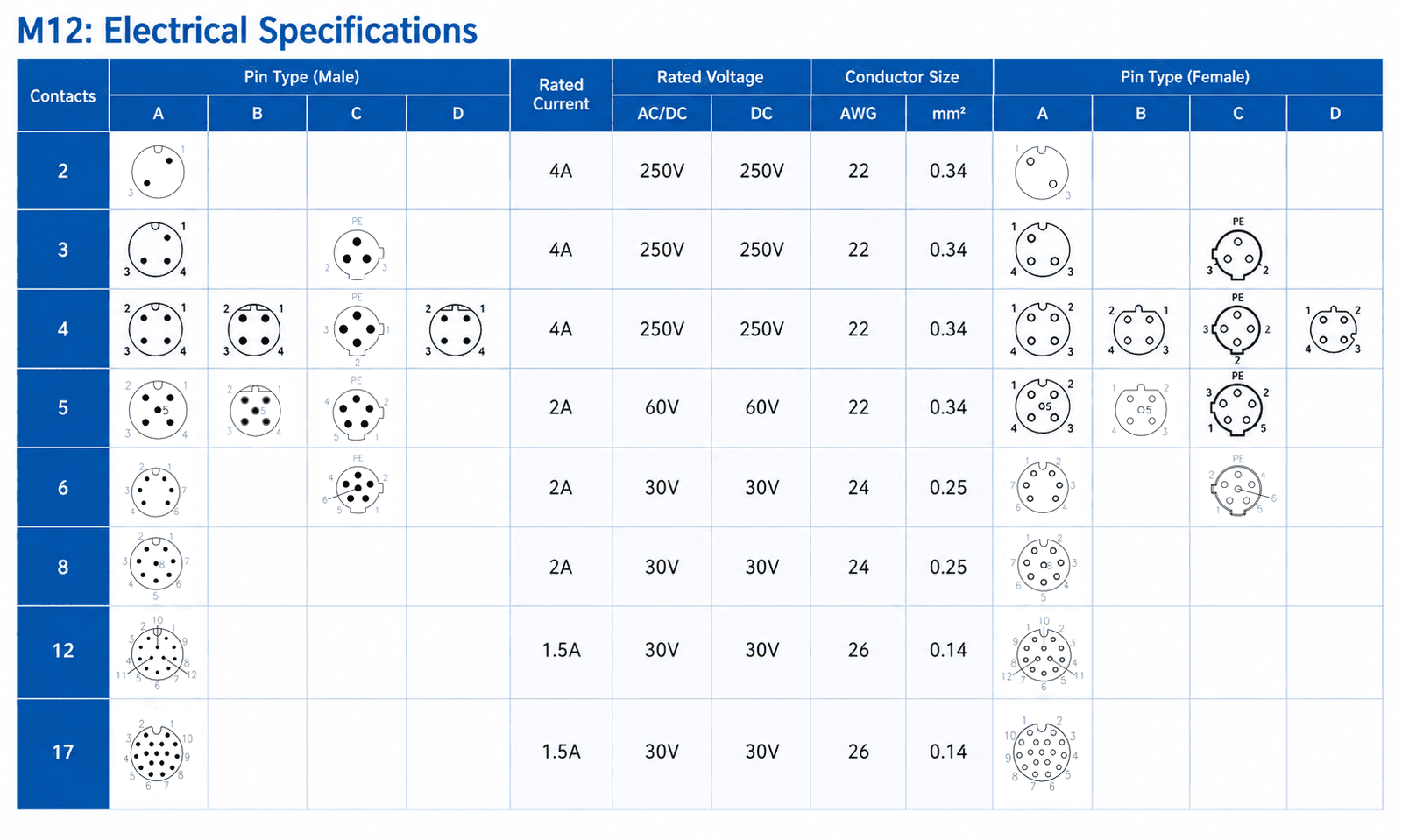
An M12 connector does not have one fixed number of pins. The M12 family includes configurations from 2 to 17 contacts, while common catalog options include 2, 3, 4, 5, 6, 7, 8, 12, and 17 contacts. The correct number depends on the coding, application, electrical requirements, and product series.
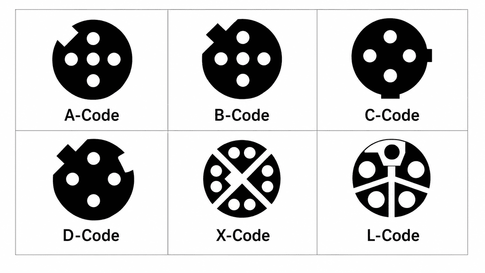
In our quotation work, a request such as “M12 4-pin male connector” is only a starting point. We still need to confirm the coding, mating side, product structure, wiring, cable, and electrical rating before we can identify the correct part.
No. M12 describes the size of the locking interface, not the number of electrical contacts.
binder explains that the M12 name comes from the connector's 12 mm metric locking thread, which provides a compact and vibration-resistant connection for industrial equipment.1 Inside that same general interface, manufacturers can use different inserts, contact arrangements, and mechanical coding.
This means the following products can all be described as M12 connectors:
| Term | What it describes | What it does not confirm |
|---|---|---|
| M12 | Locking-interface family and nominal metric size | Pin count, coding, or wiring |
| Pin count | Number of electrical contacts or positions | Application or mating compatibility |
| Coding | Keyway and contact arrangement for a defined interface family | Complete device pin function |
| Pinout | Electrical function assigned to each contact | Mechanical structure, cable, or mounting method |
For precise technical writing, contacts, positions, or poles may be more accurate than pins, because a male connector has visible pins while a female connector has socket contacts. In everyday purchasing, however, both are commonly described as 4-pin, 5-pin, or 8-pin connectors.
The standardized M12 screw-locking family extends from 2-way to 17-way, but this is a range rather than a promise that every coding and body style is available in every number.
IEC 61076-2-101:2024 describes M12 screw-locking connectors from 2-way up to 17-way for signal, data, and power transmission within the scope of that standard.2 The same IEC summary also makes clear that contact diameter varies according to the number of ways and coding. That is one reason a pin count cannot be separated from the exact connector design.
The contact counts most often seen in industrial catalogs are not every whole number between 2 and 17. They are a set of established configurations:
| Contact count | Typical role | Important caution |
|---|---|---|
| 2 | Limited-function signal or power connection | Less common; verify the exact series and interface |
| 3 | Basic sensor circuit or certain power arrangements | A 3-pin signal connector and a 2+PE power connector are different |
| 4 | Sensors, actuators, two-pair Ethernet, or DC power | Coding determines whether it is A, D, T, L, or another interface |
| 5 | Sensor functions, fieldbus, auxiliary contact, or power plus earth | The fifth contact does not have one universal function |
| 6 | Multi-signal or coding-specific power connection | Check the face, drawing, and electrical rating |
| 7 | Less-common multi-signal configuration | Availability depends strongly on the manufacturer and body style |
| 8 | A-coded multi-signal or X-coded four-pair Ethernet | Same number, different insert and cable requirements |
| 12 | High-density signal and control connections | Smaller conductors and termination space require careful review |
| 17 | Dense equipment, panel, or PCB signal interface | Exact drawing and assembly method are essential |
Manufacturer portfolios do not all use the same subset. binder's M12 A-coded range lists 3-, 4-, 5-, 8-, and 12-contact configurations,3 while NorComp's M12 series also shows 6-, 7-, and 17-contact A-coded products.4
This does not make either range incorrect. It shows why the final availability must be checked against the selected manufacturer, cable outlet, panel style, termination method, and certification requirement.
Three-, four-, and five-contact M12 connectors are the configurations most buyers encounter in ordinary sensor and actuator wiring, but their functions still depend on the coding and device circuit.
A 3-pin A-coded connector is commonly used when a sensor needs a positive supply, 0 V, and one switching signal. This is a practical arrangement for many proximity, photoelectric, and basic position sensors.
Three contacts can also appear in a power interface written as 2+PE, meaning two current-carrying conductors plus protective earth. The total number may be the same, but the connector is not a sensor substitute.
A 4-pin A-coded connector is one of the most familiar sensor and actuator interfaces. Depending on the device, the fourth available contact may support a second switching output, input, teach function, or another defined signal.
Four contacts also appear in other applications. A D-coded 4-pin connector is normally associated with two-pair Industrial Ethernet, while T-coded and some L-coded products are intended for DC power. These interfaces use different coding and must not be selected from the number alone.
The IO-Link System Description notes that sensors commonly use a 4-pin M12 plug, actuators a 5-pin plug, and IO-Link masters generally a 5-pin M12 socket.5 It also defines Pins 1, 3, and 4 for supply, return, and the C/Q line, while additional contact functions depend on the port class and equipment.
A 5-pin A-coded product provides one more available contact than a 4-pin version, but that extra contact is not automatically assigned to one standard function. It may be used for an additional signal, isolated auxiliary supply, functional earth, analog reference, or a manufacturer-specific purpose.
| Configuration | Common example | What must be verified |
|---|---|---|
| 3-pin A-coded | Basic powered sensor with one output | Device voltage and pin assignment |
| 4-pin A-coded | Sensor, actuator, or IO-Link device | Function of the additional contact and device pinout |
| 4-pin D-coded | Two-pair Industrial Ethernet | Coding, shielding, cable construction, and network requirement |
| 5-pin A-coded | Additional signal or application-specific circuit | Exact use of Pins 2 and 5 |
| 5-pin B-coded | Fieldbus connection | Protocol, shielding, and manufacturer drawing |
| 5-contact power code | Power conductors plus PE or FE | Coding, voltage, current, and grounding arrangement |
For complete A-coded wiring tables and wire-color guidance, use our M12 A-coded 3-pin, 4-pin, and 5-pin pinout guide. This article intentionally does not repeat those full pinout tables because the selection question is different.
Higher-contact-count M12 connectors are mainly used when several signals, channels, or data pairs must pass through one compact interface.
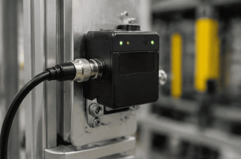
Six- and seven-contact products are less universal than 3-, 4-, or 5-pin sensor connectors. They may be used for equipment-specific signals, feedback devices, compact control interfaces, or a coding-specific power arrangement.
When replacing one of these connectors, I do not assume that a visually similar product has the same contact positions or rear termination. A clear mating-face photo and the manufacturer's drawing are more useful than a side-view photo alone.
An 8-pin connector can describe two very different product families:
IEC 61076-2-109 specifies M12 × 1 connectors for data-transmission frequencies up to 500 MHz, including applications such as vision systems and data acquisition.6 An X-coded head must still be paired with the correct data cable, shielding, termination, and equipment; eight contacts alone do not guarantee network performance.
See our dedicated M12 8-pin connector guide for the A-coded and X-coded face, wiring, cable, and application differences.
Twelve- and seventeen-contact M12 products are used when a compact connector must carry many separate low-voltage signals. Possible applications include multi-channel sensing, equipment control, test fixtures, compact panels, and device-specific interfaces.
| Higher pin count | Why it may be selected | Main design risk |
|---|---|---|
| 6 or 7 | More equipment-specific signal paths than a 5-pin interface provides | Assuming a universal pinout |
| 8 A-coded | Several signals through one circular connection | Confusing it with X-coded Ethernet |
| 8 X-coded | Four controlled data pairs | Using an unsuitable cable or shield termination |
| 12 | Dense signal wiring in a compact interface | Limited conductor and assembly space |
| 17 | Maximum-density signal connection within the relevant M12 family | PCB footprint, soldering, and drawing mismatch |
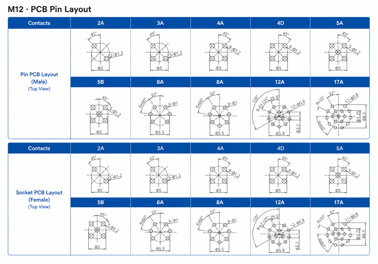
The M12 mating interface remains compact, so a higher contact count can make termination and inspection more demanding. A 12- or 17-contact connector should be approved from the exact face drawing, wiring diagram, PCB footprint where applicable, and a physical sample before volume production.
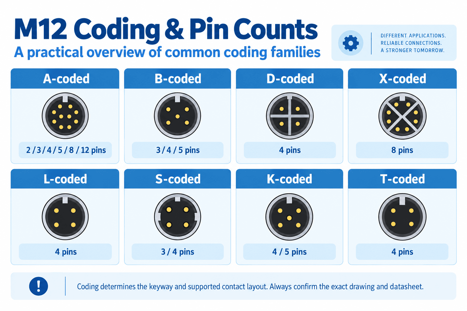
Coding defines the keyway and contact arrangement for a particular signal, data, or power family, so each code supports only certain contact layouts.
The table below is a practical selection overview. It is not a replacement for the latest standard or the exact product drawing.
| M12 coding | Common contact arrangement | Typical use | Selection note |
|---|---|---|---|
| A-coded | Broad range; commonly 3, 4, 5, 8, and 12, with other counts available by series | Sensors, actuators, general signals, some low-voltage power | Pin function is device-dependent |
| B-coded | Commonly 4 or 5 | PROFIBUS and other fieldbus applications | Check the network and shield requirement |
| D-coded | Normally 4 | Two-pair Industrial Ethernet | Not interchangeable with 4-pin A-coded |
| X-coded | 8 | Four-pair Industrial Ethernet | Requires the appropriate data-channel construction |
| S-coded | 2+PE or 3+PE | AC power | PE may be written separately from the active conductors |
| T-coded | 4 positions | DC power | Do not confuse with 4-pin signal or Ethernet products |
| K-coded | 4+PE | AC power | Larger power contacts and different coding |
| L-coded | 4 positions or 4+FE | DC power | FE is optional in some variants |
| M-coded | 5+PE | AC power with an auxiliary or brake circuit | Six physical contacts may be described as 5+PE |
Phoenix Contact's M12 Power overview shows S-, K-, M-, T-, and L-coded circuits ranging from 2+PE to 5+PE.7 The current IEC 61076-2-111:2025 scope covers 4- to 6-way M12 screw-locking power connectors, with electrical ratings determined by the coding and connector design.8
This is why catalogs do not always describe power-contact counts in the same way. One may say 5-position, while another says 4+PE or 4+FE. Buyers should read the full designation instead of comparing only the first number.
The same number of contacts does not guarantee the same keyway, pin arrangement, electrical function, cable, or mating compatibility.
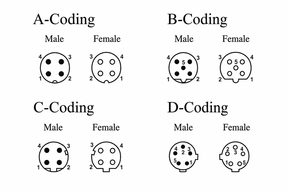
Two comparisons explain the problem clearly:
| Same contact count | First connector | Second connector | Why they differ |
|---|---|---|---|
| 4 contacts | A-coded sensor or actuator connector | D-coded Industrial Ethernet connector | Different keyway, use, cable, and pin function |
| 8 contacts | A-coded multi-signal connector | X-coded four-pair Ethernet connector | Different insert geometry, contact grouping, and data requirements |
Even two connectors with matching coding and pin count may still differ in:
Our M12 connector types guide organizes these selection dimensions in more detail. For this question, the essential rule is simple: count the contacts, but never approve the product from the count alone.
No. More pins provide more electrical paths; they do not automatically provide more current, higher voltage, faster data, or better quality.
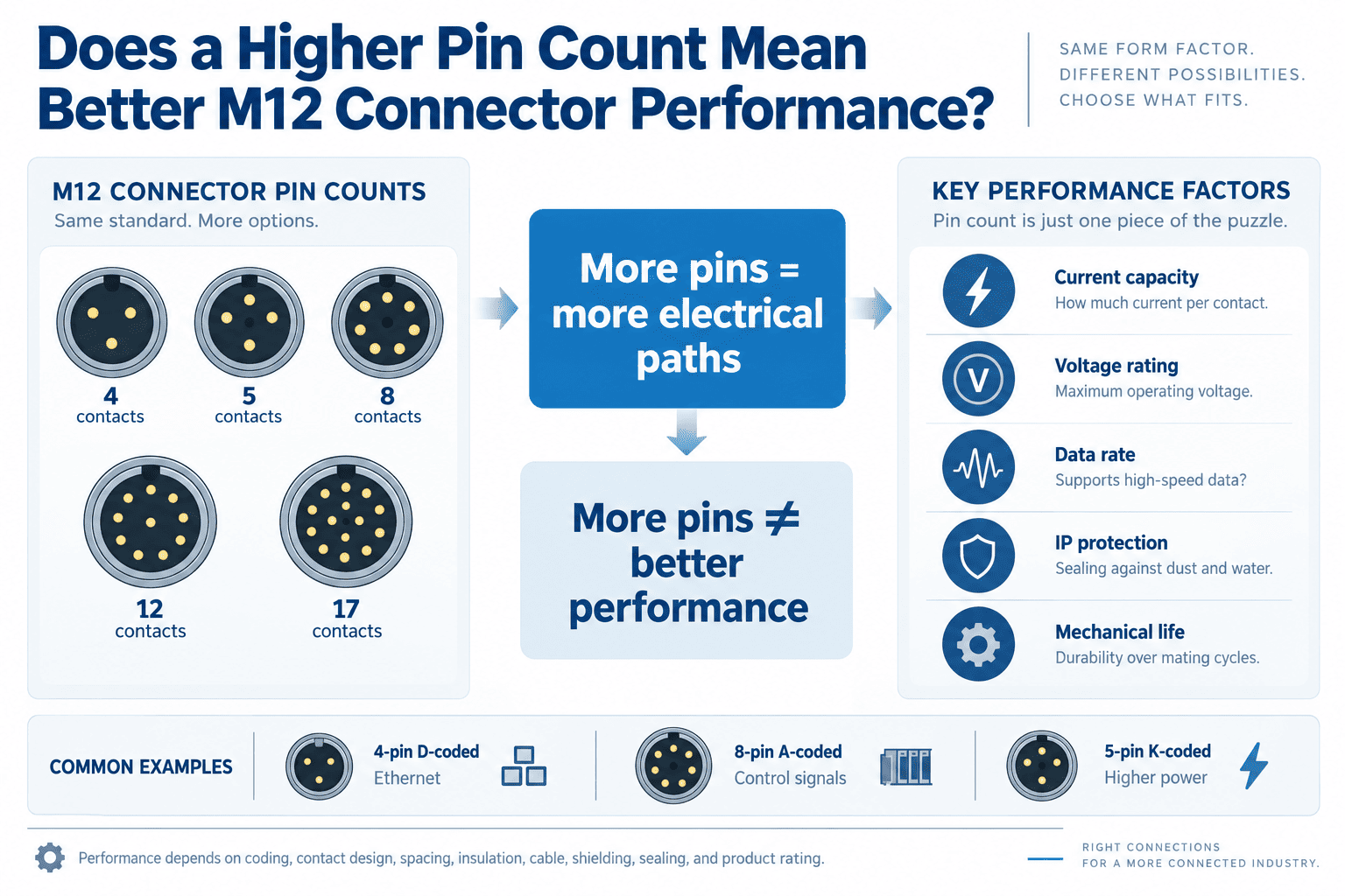
A 4-contact D-coded connector can serve a defined Ethernet application, while an 8-contact A-coded connector may carry only low-frequency control signals. A 5-contact K-coded power connector can carry much more current than a dense 12- or 17-contact signal connector, depending on the exact product rating.
| Requirement | What determines it | Why pin count is insufficient |
|---|---|---|
| Current capacity | Contact size, material, wire cross-section, temperature, and derating | More contacts may be smaller or more densely arranged |
| Voltage rating | Coding, spacing, insulation, pollution conditions, and standard | The same count appears in signal and power families |
| Data rate | Contact geometry, pair arrangement, cable category, shielding, and complete channel | Eight contacts can be A-coded signal or X-coded Ethernet |
| Waterproof protection | Sealing structure, assembly, mating, tightening, and tested product | Pin count does not create an IP rating |
| Mechanical life | Contact system, plating, housing, and test specification | Contact quantity alone says nothing about durability |
When I compare alternatives for a project, I start from the required circuits and protocol, then check the product-specific datasheet. Selecting the highest pin count “for future use” can add unnecessary cable diameter, termination work, cost, and inspection complexity.
Count the contacts from the mating face, identify the keyway, and confirm whether the drawing shows the mating side or wiring side.
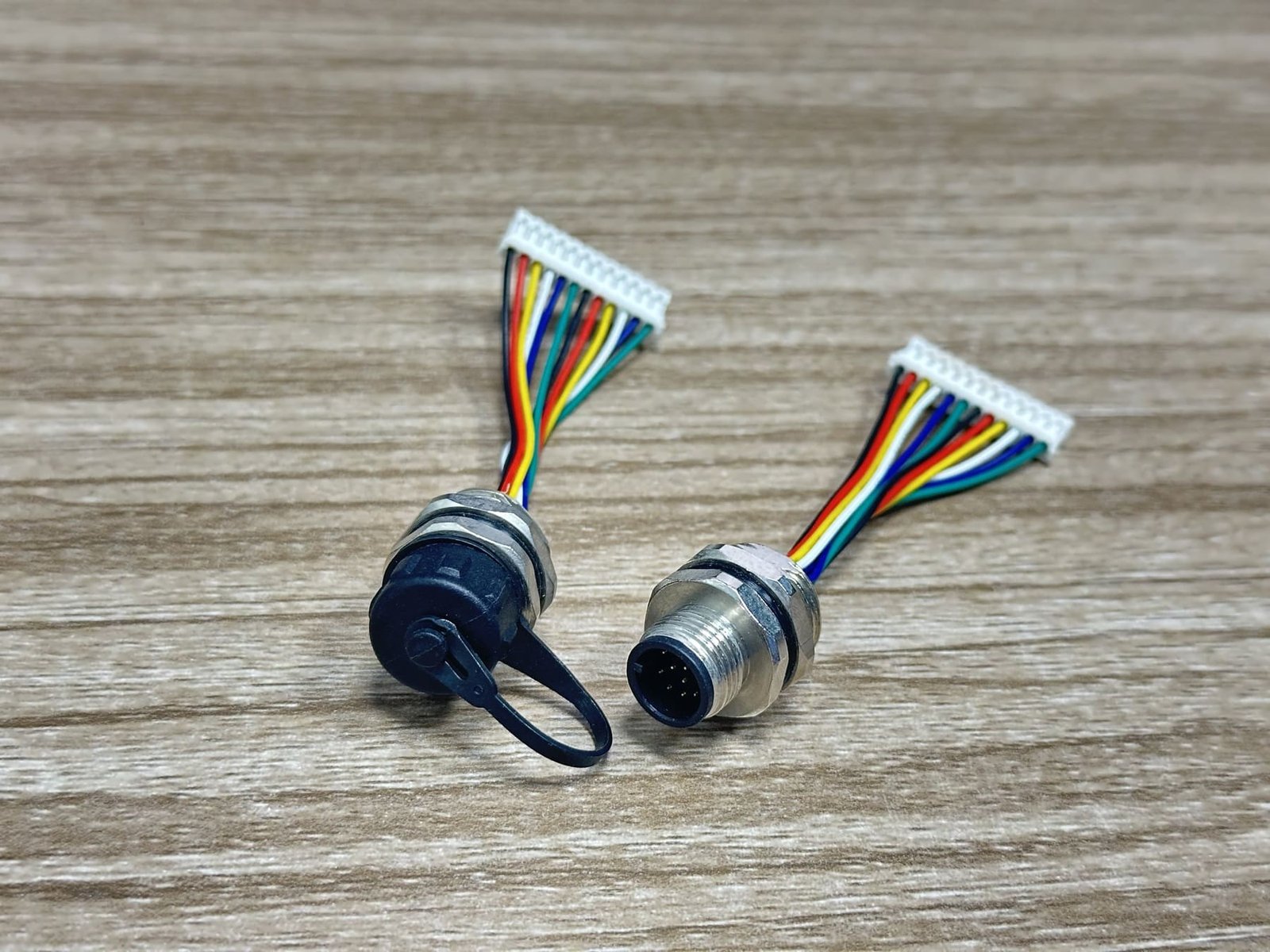
A male M12 connector has visible contact pins. A female M12 connector has socket openings. Both may be called “4-pin” in a product inquiry, but their front views are mirrored when they mate.
Use this sequence when identifying an unknown connector:
| Identification evidence | What it can confirm |
|---|---|
| Clear mating-face photo | Pin count, gender, and likely coding |
| Side-view photo | Straight/angled shape, coupling nut, and cable outlet |
| Equipment model label | Original manufacturer documentation and protocol |
| Wiring diagram | Contact functions and viewing direction |
| Panel or PCB drawing | Mounting dimensions and rear termination |
| Old mating sample | Physical fit and keyway comparison |
A side-view photo alone is usually not enough because many M12 housings look almost identical from the outside.
Provide the application, coding, pin count, gender, structure, wiring, electrical rating, cable requirements, and quantity. Unknown details can be confirmed from photos, drawings, or a sample.
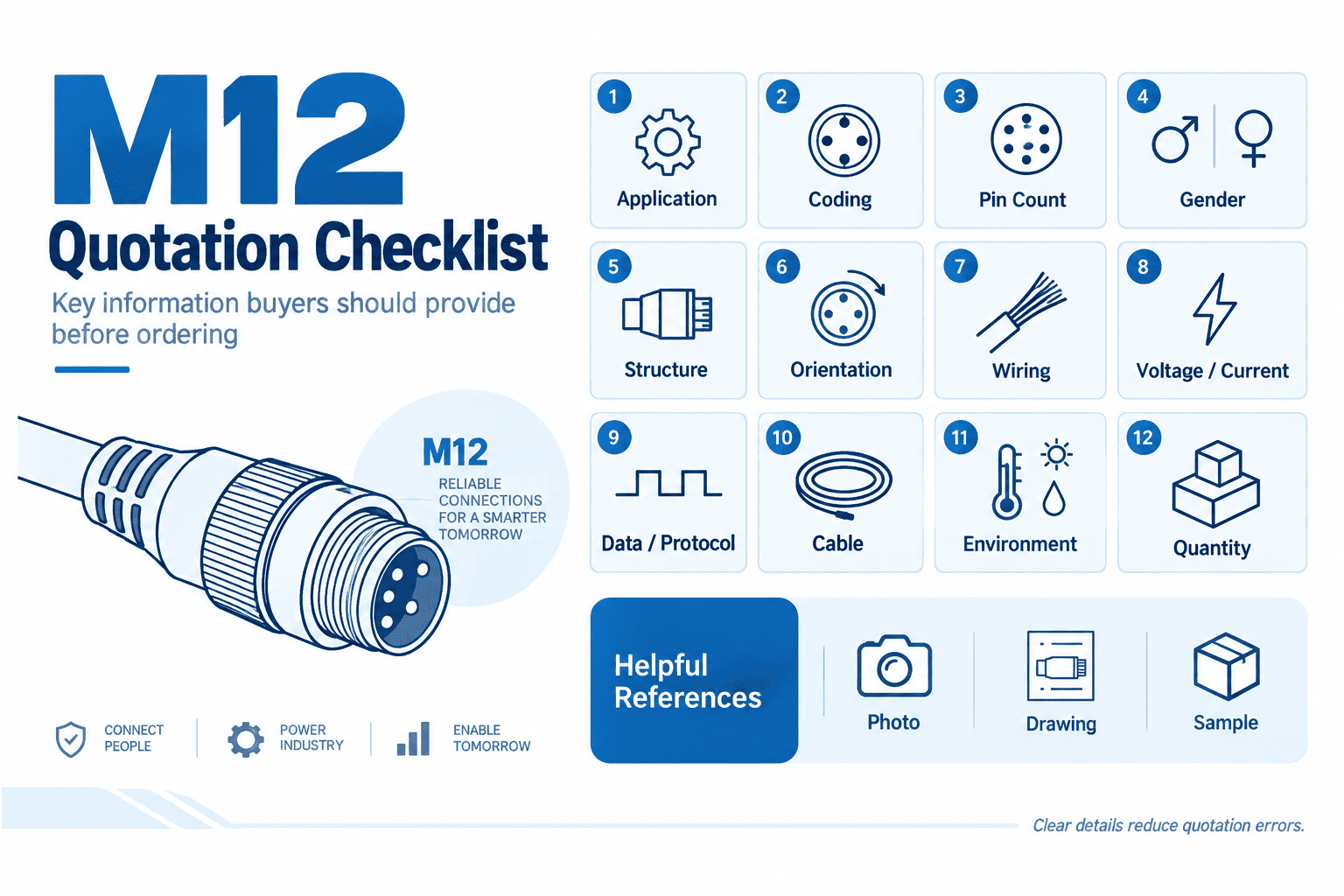
When a customer sends us only “M12 4-pin connector,” these are the questions I use to turn it into a producible specification:
| Information | Example | Why we need it |
|---|---|---|
| Application | Proximity sensor, encoder, Ethernet switch, motor | Narrows the correct coding and product family |
| Coding | A, B, D, X, S, T, K, L, or M | Confirms keying and mating compatibility |
| Contact count | 3, 4, 5, 8, 12, or another required layout | Confirms the insert configuration |
| Gender | Male pins or female sockets | Confirms the mating side |
| Product structure | Molded cable, field-wireable, panel, or PCB | Determines housing and termination |
| Orientation | Straight or right-angle | Affects cable routing and installation space |
| Wiring | Pin-to-pin table or device pinout | Prevents electrical mismatch |
| Electrical rating | Voltage and current per circuit | Confirms contact and cable suitability |
| Data requirement | Protocol and transmission rate | Determines coding, cable pairs, and shielding |
| Cable | Length, wire gauge, PVC/PUR, flexing, shielding | Defines the complete assembly |
| Environment | IP requirement, oil, temperature, vibration, movement | Defines sealing and material requirements |
| Quantity | Sample and expected batch volume | Supports quotation and production planning |
If you do not know all these details, send what you already have. A clear front-face photo, equipment model, old sample, and wiring diagram are usually enough for an initial review.
You can also browse our M12 4-pin connector structures or send your information through the NITAI contact page. We confirm the remaining details before recommending a sample.
No. Four contacts are common, but M12 connectors are available in multiple configurations from 2-way to 17-way within the relevant standard family.
Three-, four-, and five-contact A-coded connectors are especially common in sensor and actuator wiring. Four-contact D-coded and eight-contact X-coded products are common in Industrial Ethernet. The answer therefore depends on the application rather than one universal market winner.
No. The contact arrangements are different. Select a plug and socket with matching coding, contact count, and gender.
No. A-coded, D-coded, and power-coded 4-contact products serve different functions. Even within one coding, device manufacturers may assign optional contacts differently.
No. X-coded 8-pin connectors are designed for four-pair Industrial Ethernet, while A-coded 8-pin connectors are commonly used for multiple signals or equipment-specific circuits.
The locking interface remains in the M12 family, but the insert is denser and the rear body or termination area may differ. Always check the complete dimensional drawing instead of assuming every M12 housing has identical dimensions.
Naming varies. A supplier may describe a connector as 5-position, 4+PE, or 4+FE. Read the complete contact designation and drawing so that protective earth or functional earth is not mistaken for another signal conductor.
Only when the equipment design and approved wiring allow it. An unused electrical contact does not change the mechanical coding or pin layout. The final assembly should still follow the device drawing and project documentation.
Not automatically. Current capacity depends on the contact design, conductor size, temperature, termination, and product rating. A lower-contact-count power connector may carry much more current than a high-density signal connector.
M12 connectors do not have one fixed number of pins. The relevant standard family extends from 2-way to 17-way, while commonly encountered configurations include 2, 3, 4, 5, 6, 7, 8, 12, and 17 contacts.
The number only tells you how many electrical contact positions are present. It does not confirm the coding, application, pinout, gender, cable, mounting method, electrical rating, or mating compatibility.
For a reliable selection, use this order:
If you have only a connector photo or an old cable, send the mating-face image, equipment information, and any available pinout to NITAI. We can identify the missing specifications and help prepare the correct standard product or custom cable assembly for sample testing.
[“M12 Connectors – Complete Guide to Our Most Prominent Series,” binder](https://www.binder-connector.com/en/news/m12-connectors-complete-guide-to-our-most-prominent-series). binder explains that M12 refers to the 12 mm metric locking thread rather than a twelve-contact layout. Evidence role: definition; source type: connector manufacturer. Supports: what the M12 designation means. Scope note: the page describes binder's portfolio, so individual NITAI products still require their own drawings and ratings. ↩
[“IEC 61076-2-101:2024,” International Electrotechnical Commission](https://webstore.iec.ch/en/publication/77773). The official IEC summary describes M12 screw-locking circular connectors from 2-way through 17-way and notes that contact dimensions depend on the number of ways and coding. Evidence role: primary standard; source type: international standards body. Supports: the overall M12 contact-count range and the need to distinguish configuration from coding. Scope note: the standard's maximum voltage, current, and frequency are scope limits, not automatic ratings for every product. ↩
[“M12 A-Code – A-Coded Connector,” binder](https://www.binder-usa.com/us-en/products/automation-technology/m12-a). binder lists 3-, 4-, 5-, 8-, and 12-pin A-coded products across several connection forms. Evidence role: product-range example; source type: connector manufacturer. Supports: common A-coded contact counts. Scope note: this is one manufacturer's range and does not prove that every supplier offers the same variants. ↩
[“M12 Connector Series,” NorComp](https://www.norcomp.net/series/m12-series-circular-connector). The official series table includes A-coded configurations such as 6, 7, 12, and 17 contacts, together with B-, D-, X-, and power-coded examples. Evidence role: product-range example; source type: connector manufacturer. Supports: less-common high-contact-count options and coding-specific availability. Scope note: availability remains model- and manufacturer-dependent. ↩
[“IO-Link System Description: Technology and Application,” IO-Link Community](https://io-link.com/fileadmin/user_upload/Downloads/About_IO-Link/IO-Link_System_Description_eng_2018.pdf). The industry association describes typical M12 interfaces for sensors, actuators, and masters and explains the roles of Pins 1, 3, and 4 and the port-dependent use of additional contacts. Evidence role: protocol reference; source type: industry association. Supports: why 4- and 5-contact M12 products are common in IO-Link systems and why extra contacts are device-dependent. Scope note: the exact device datasheet remains authoritative for a particular port. ↩
[“IEC 61076-2-109:2014,” International Electrotechnical Commission](https://webstore.iec.ch/en/publication/4425). The official IEC summary covers M12 × 1 connectors for data-transmission frequencies up to 500 MHz and cites vision and data-acquisition applications. Evidence role: primary standard; source type: international standards body. Supports: the specialized data role of the X-coded M12 family. Scope note: connector compliance alone does not establish the performance of the entire installed Ethernet channel. ↩
[“Get Amped With M12 Power,” Phoenix Contact](https://www.phoenixcontact.com/en-us/us-lp-m12power). Phoenix Contact illustrates S-, K-, M-, T-, and L-coded circuits using 2+PE, 3+PE, 4+PE, 5+PE, four-position, and 4+FE descriptions. Evidence role: application and product-family reference; source type: connector manufacturer. Supports: power-code contact notation and the reason PE or FE may be listed separately. Scope note: the published ratings apply to the described Phoenix Contact products and must not be copied automatically to another model. ↩
[“IEC 61076-2-111:2025,” International Electrotechnical Commission](https://webstore.iec.ch/en/publication/89862). The current IEC scope describes 4- to 6-way M12 screw-locking power connectors with current and voltage ratings defined by coding. Evidence role: primary standard; source type: international standards body. Supports: the contact-count range and coding-specific nature of M12 power interfaces. Scope note: use the exact product datasheet for final ratings and compliance. ↩
A relay module is a ready-to-wire switching interface that allows a low-power control signal to operate a separate…
Choosing an M12 connector manufacturer is not simply a matter of selecting the best-known name. The right supplier…
An M8 connector is used when industrial equipment needs reliable signal, power, or data connections in a compact…
NITAI manufactures terminal blocks, M8/M12 waterproof connectors and industrial distribution modules for global OEMs, distributors and automation customers.
Leave a Reply