Sep 10, 2026
Top M12 Connector Manufacturers: 10 Global Brands Compared
Choosing an M12 connector manufacturer is not simply a matter of selecting the best-known name. The right supplier…

Most modern PLC control systems commonly use 24 VDC, but a PLC does not have one universal voltage. Depending on the exact model, the controller itself may be powered by 24 VDC, 12 VDC, or 100–240 VAC. Its digital inputs may use 24 VDC or another specified level, its analog channels may read signals such as 0–10 V or 4–20 mA, and its outputs may switch a separate field-load supply. The correct answer therefore comes from the full part number and wiring manual—not from the word “PLC” alone.
When we review a PLC-related wiring requirement at NITAI, the first question is not simply, “Is this a 24 V PLC?” We separate the controller supply, I/O signal, output circuit, and field-device supply. Those voltages may be related, but they are not automatically the same.
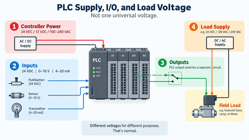
This overview separates PLC/CPU power, input signals, output switching, and the external field-load supply. AC input or 24 VDC controller power, 24 VDC digital signals, 0–10 V or 4–20 mA analog signals, and externally powered loads belong to different electrical paths; one voltage should never be assumed to power the entire PLC system.
| Question | Short answer |
|---|---|
| What voltage do most PLC systems use? | 24 VDC is very common in modern control cabinets. |
| Do all PLCs run on 24 VDC? | No. Some PLC CPUs accept AC mains, 12 VDC, or other model-specific supplies. |
| Is PLC input voltage always the same as CPU supply voltage? | No. The input module has its own accepted signal range and thresholds. |
| Does a PLC output create the load voltage? | Not necessarily. Transistor and relay outputs usually switch an external field supply. |
| Can a 24 V PLC control a 230 VAC load? | Yes, if a correctly rated relay, contactor, solid-state device, or suitable output module provides the required separation and switching capacity. |
IEC 61131-2 covers equipment requirements and tests for PLCs, PACs, and associated peripherals, but it does not turn one voltage into a universal answer for every controller and I/O configuration.1 That is why the exact manufacturer documentation must remain the final authority.
No. Twenty-four volts DC is common, but PLC supply voltage depends on the manufacturer, controller family, and exact catalog number.
The easiest way to see this is to compare official product information. OMRON lists both 100–240 VAC supply models and 24 VDC supply models within its CP1E family. Rockwell Automation’s Micro800 selection guide includes controller options with 120/240 VAC, 24 VDC, and, for certain models, 12 VDC power. A Siemens S7-1200 CPU 1212C DC/DC/DC example uses a 20.4–28.8 VDC supply and has 24 VDC digital I/O plus 0–10 V analog inputs.234
| Official example | Controller power | I/O examples shown by the manufacturer | What the example proves |
|---|---|---|---|
| OMRON CP1E family | 100–240 VAC or 24 VDC, depending on model | I/O varies by CPU suffix and configuration | Even one PLC family may contain AC- and DC-powered CPUs. |
| Rockwell Micro800 family | 120/240 VAC, 24 VDC, or selected 12 VDC options | 24 VDC source/sink, relay, AC input, and analog variants | Supply, input type, and output type are separate selection fields. |
| Siemens S7-1200 CPU 1212C DC/DC/DC example | 20.4–28.8 VDC | 24 VDC DI, 24 VDC DO, and 0–10 V AI | One controller can use different voltage categories for power and signals. |
| AutomationDirect CLICK family | 24 VDC PLC power | Logic-side and field-side current are budgeted separately | A 24 VDC family still requires more than one power calculation. |
These values are examples, not substitutes for a datasheet. A product-family name is often not enough because suffixes such as AC, DC, relay, source, or sink may identify electrically different versions.
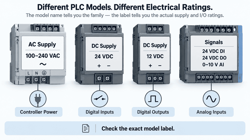
PLC nameplates and terminal markings may identify controller power, input type, analog range, and output technology separately. Labels such as POWER: 24 VDC, POWER: 100–240 VAC, DI: 24 VDC, AI: 0–10 V, or OUTPUT: RELAY are model-specific examples, which is why the complete catalog number is more reliable than the general phrase “24 V PLC.”
“PLC voltage” can refer to at least six different electrical values, so the term must be defined before any component is selected or wired.
This is the main reason simple answers become misleading. A technician may be asking what powers the CPU, while a buyer may be asking what sensor voltage is compatible. Another person may mean the voltage switched by a relay output.
| Voltage layer | What it powers or represents | Common examples | Where to verify it |
|---|---|---|---|
| Facility supply | Power available in the machine or building | 120 VAC, 230 VAC, 400 VAC three-phase | Electrical drawing and local supply |
| PLC controller supply | Power entering the CPU or PLC power supply | 24 VDC, 12 VDC, 100–240 VAC | CPU nameplate and hardware manual |
| Internal or backplane power | Low-voltage power used inside the PLC/I/O system | 5 VDC or another internal rail | System power-budget documentation |
| Digital input signal | Voltage interpreted as ON or OFF | Frequently 24 VDC; AC inputs also exist | Input-module specification |
| Analog signal | A continuously variable measurement or command | 0–10 V, ±10 V, 4–20 mA | Analog-module and device datasheets |
| Output/load circuit | External voltage switched or controlled by the output | 24 VDC, 120 VAC, 230 VAC, or another rated circuit | Output type, contact rating, and load data |
Internal voltage is especially easy to misunderstand. Rockwell’s POINT I/O documentation gives an example in which incoming 24 VDC is converted to 5 VDC backplane power. The same guide separately lists 24 VDC input and output ratings for field-side channels.5 The presence of 5 V inside that system does not mean an installer should apply 5 V to terminals intended for a 24 VDC supply or input.
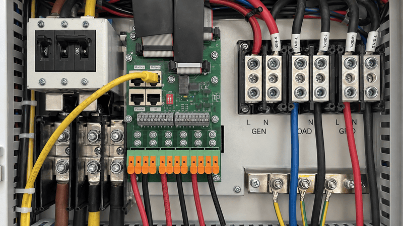
A PLC cabinet can contain six separate voltage domains: facility supply, controller supply, internal or backplane power, digital input signals, analog signals, and output/load power. Values such as 100–240 VAC, 24 VDC, internal bus voltage, 0–10 V, and 4–20 mA describe different parts of the system, while protective earth, neutral, and 0 V retain different functions.
Twenty-four volts DC is common because many industrial controllers, sensors, interface devices, and solenoids are designed around it, making one control-voltage network practical to distribute and troubleshoot.
Using one established DC control voltage can simplify panel design:
However, “common” does not mean “automatically compatible.” Two devices marked 24 VDC may still differ in allowable range, current consumption, surge current, polarity, PNP/NPN behavior, channel common, isolation, and grounding requirements.
Rockwell’s Micro800 technical data, for example, does not describe a 24 VDC input using the nominal voltage alone. It also specifies ON-state and OFF-state voltage ranges, input current, output voltage drop, current limits, and temperature-related ratings.6 Those details determine whether a real circuit works reliably.
| Check beyond the 24 V label | Why it matters |
|---|---|
| Operating voltage range | The device must remain within its allowed range during normal operation and transients. |
| Steady-state current | The power supply must support the simultaneous load. |
| Inrush or surge current | A load may demand substantially more current at startup. |
| Source/sink relationship | A PNP sensor and an NPN sensor do not connect to every input in the same way. |
| Common-terminal arrangement | Channel groups may share a common or be isolated. |
| Output voltage drop and leakage | Electronic outputs are not ideal mechanical switches. |
| Ambient-temperature derating | Allowable channel or supply current can decrease at higher temperature. |
Yes. Some PLCs accept 100–240 VAC directly, while others require an external power supply that converts AC mains to 24 VDC.
An AC-powered PLC still operates with low-voltage electronics internally. “AC-powered” describes the voltage accepted at the controller’s power terminals; it does not mean every input and output uses AC.
The OMRON CP1E specification illustrates this clearly: its AC supply models are rated for 100–240 VAC, while its DC supply models are rated for 24 VDC. The same page also lists different operating ranges, consumption values, and inrush current for those variants.
| Architecture | Typical power path | Advantages | Points to verify |
|---|---|---|---|
| AC-input PLC | AC mains → PLC internal supply | Fewer separate power components for the CPU | Exact AC range, frequency, protective device, grounding, and available auxiliary DC power |
| DC-input PLC | AC mains → external 24 VDC supply → PLC | One DC supply can support a planned control-voltage system | Total current, inrush, branch protection, voltage drop, isolation, and redundancy |
| DC machine or mobile system | Battery/DC bus → conditioning or DC/DC conversion → PLC | Avoids unnecessary AC conversion | Bus variation, cranking dips, charging voltage, transients, and approved input range |
One design is not automatically better. The correct choice depends on the available supply, cabinet architecture, service requirements, safety design, and exact PLC model.
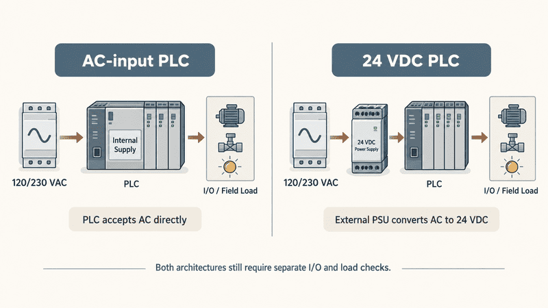
An AC-powered PLC accepts a specified AC supply at its power terminals, while a DC-powered PLC receives 24 VDC or another specified voltage from an external power supply. In both arrangements, the input, output, and field-load circuits remain separate branches that require their own voltage, current, protection, and wiring checks.
Many PLC digital inputs use nominal 24 VDC signals, but PLC inputs may also be designed for AC, lower-voltage DC, thermocouples, RTDs, or analog voltage and current signals.
For a digital input, the PLC does not merely ask whether voltage is present. The module defines an ON-state range, an OFF-state range, input current, response time, and often a sink/source wiring arrangement. A meter reading of “about 24 V” is therefore only one part of diagnosis.
Rockwell’s Micro800 family selection guide includes examples of 24 VDC/AC inputs and 120 VAC inputs, depending on the selected controller. Its detailed technical data also lists model-specific ON/OFF thresholds rather than treating every nonzero voltage as ON.
| Input type | Typical use | What must match |
|---|---|---|
| 24 VDC sink/source input | Proximity sensors, photoelectric sensors, switches | Voltage range, PNP/NPN circuit, current, common terminal, and isolation |
| 120 VAC input | Existing AC control circuits | AC rating, frequency, ON/OFF thresholds, isolation, and local safety requirements |
| High-speed DC input | Encoder or fast pulse | Voltage plus minimum pulse width, input frequency, filtering, and wiring |
| Dry-contact input circuit | Pushbutton or relay contact | The PLC/input supply still provides the sensing voltage; the contact itself does not generate voltage |
Analog signal voltage is not the same as PLC supply voltage. Phoenix Contact lists one analog module with a 24 VDC I/O supply range of 19.2–30 VDC while the module measures 0–10 V analog signals.7 That is a direct example of one module using two different voltage concepts.
| Analog signal | What it represents | Important checks |
|---|---|---|
| 0–10 V | Process value across a voltage range | Input impedance, common reference, shield, maximum permissible voltage |
| ±10 V | Bidirectional command or measurement | Polarity, bipolar range, isolation, common |
| 4–20 mA | Current-loop process signal | Loop power, active/passive channel, burden, open-circuit behavior |
| RTD or thermocouple | Temperature sensor signal | Sensor type, compensation, wiring method, dedicated module |
Do not power a 0–10 V sensor loop by assuming the PLC’s analog terminal supplies 10 V. Some devices provide an excitation terminal; others only measure a signal. The wiring diagram must show which device powers the loop.
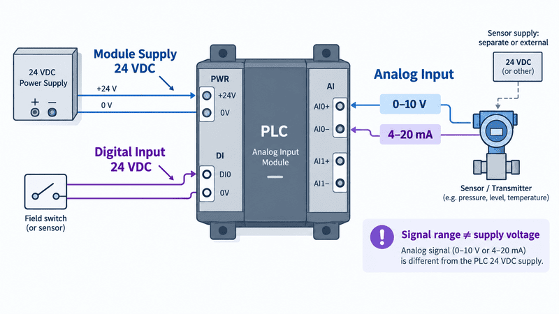
A three-wire 24 VDC sensor normally has separate L+, Signal, and 0 V/Common conductors, while 0–10 V and 4–20 mA circuits must distinguish the measured signal from the transmitter or loop supply. These are representative signal paths; the exact PNP/NPN or active/passive arrangement must come from the selected device and PLC module manuals.
There is no single PLC output voltage. The answer depends on whether the output is transistor, relay, triac, or analog—and on the external power connected to that output circuit.
A PLC program turns an output command ON or OFF, but the hardware determines how electrical power reaches the load.
| Output type | What it does | Typical voltage domain | Key limitation |
|---|---|---|---|
| Transistor output | Electronically switches DC current | Commonly a specified DC range such as 24 VDC | Requires correct source/sink polarity and external field supply; has current, leakage, and voltage-drop limits |
| Relay output | Opens or closes an isolated mechanical contact | May switch rated AC or DC circuits | Contact rating depends on voltage, load type, inrush, switching frequency, and expected life |
| Triac output | Electronically switches AC | Model-specific AC range | Not for DC loads; leakage and minimum-load behavior must be checked |
| Analog voltage output | Produces a proportional voltage command | Often 0–10 V or ±10 V on suitable modules | Limited current; intended as a signal, not a general-purpose load supply |
| Analog current output | Regulates a current-loop signal | Often 4–20 mA or 0–20 mA | Loop topology, compliance voltage, and load resistance must match |
A transistor output normally switches a user-supplied DC field circuit. It should not be treated like an unlimited 24 VDC power source. A relay output provides contacts, but the contacts do not generate voltage; the external load supply is wired through them.
OMRON’s relay explanation shows the fundamental separation: current through the coil moves the contact between NC and NO states.%%%FOOTNOTE_REF8%%% [Rockwell’s controller data](https://literature.rockwellautomation.com/idc/groups/literature/documents/td/2080-td001-en-p.pdf) then demonstrates why the exact output rating matters: relay and transistor ratings differ, and allowable current can change with voltage, load type, and temperature.
The basic power path is:
24 VDC field supply → PLC transistor output circuit → 24 VDC load → 0 V return
Whether the output is sourcing or sinking changes the terminal arrangement. The output manual—not a generic online diagram—must decide the wiring.
The basic power path is:
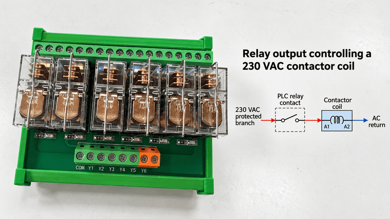
230 VAC protected branch → PLC relay contact → correctly rated contactor coil → AC return
The PLC may itself run on 24 VDC while the relay contact switches a separate 230 VAC circuit. This is possible only when the contact rating, insulation, overcurrent protection, coil inrush, suppression, wiring separation, and applicable safety rules are satisfied.
DC transistor, relay, AC triac, and analog outputs perform different electrical jobs. The field supply normally originates outside the PLC: a transistor may switch a DC solenoid, a relay contact may switch a separate AC or DC circuit, a triac controls a suitable AC load, and an analog output sends a limited command signal rather than general load power.
PLC supply voltage powers the controller; field-load voltage powers the sensor, valve, relay, contactor, lamp, or other device being monitored or controlled.
They may come from the same 24 VDC power supply, from separated 24 VDC branches, or from completely different sources. The correct architecture depends on noise, isolation, current, safety, availability, and protection requirements.
| Application | PLC/controller side | Field side | What the output actually does |
|---|---|---|---|
| 24 VDC proximity sensor | PLC may use 24 VDC | Sensor uses 24 VDC | Sensor signal drives a compatible PLC input |
| 24 VDC solenoid valve | PLC may use 24 VDC | Valve uses a protected 24 VDC branch | PLC transistor or interposing relay switches valve current |
| 230 VAC contactor coil | PLC may use 24 VDC | Coil uses 230 VAC | Rated relay/contactor interface switches the AC coil circuit |
| 4–20 mA transmitter | PLC may use 24 VDC | Loop supply may be external or device-provided | Analog input measures loop current |
| Variable-frequency drive command | PLC may use 24 VDC | Drive has its own mains and DC bus | PLC sends digital, analog, pulse, or network commands; it does not power the motor |
This distinction is also important during troubleshooting. A CPU can be powered and communicating while the field supply is missing. Conversely, a field device can be energized while the PLC input common is wired incorrectly, so the PLC never sees a valid ON signal.
Use an interface, relay, or distribution module when the circuit needs organized wiring, signal adaptation, galvanic separation, higher switching capacity, replaceable protection, or controlled power distribution—not simply because a PLC is present.
Weidmüller describes both passive and active PLC interface modules with functions such as fuses, disconnectors, and relays, and it separately identifies relay-isolated interface modules for PLC/DCS connections.9 This is useful because “interface module” is a functional category, not one universal circuit.
| Module type | Main job | What it does not automatically do |
|---|---|---|
| Passive terminal/interface module | Converts a high-density PLC connector into organized field terminals | It does not normally change the signal voltage or increase output power |
| Relay interface module | Uses a control signal to switch a separate contact circuit and can provide separation | It is not universally suitable for every AC/DC load or inrush current |
| Solid-state interface | Provides fast electronic switching with no mechanical contacts | It still has voltage, current, leakage, heat, and AC/DC limitations |
| Signal conditioner or isolator | Converts, scales, or isolates analog/discrete signals | It cannot be selected without knowing input, output, power, and isolation requirements |
| DC distribution module | Distributes a DC supply to multiple branches | Distribution alone does not guarantee individual branch protection |
| Fused or electronic protection module | Protects and, in some designs, monitors individual load branches | It must be coordinated with supply capacity, conductor size, and load behavior |
For example, Phoenix Contact lists multi-channel electronic circuit breakers designed to protect multiple 24 VDC loads against overload and short circuit.10 That illustrates the difference between merely splitting 24 VDC and distributing it through protected branches.
If you need a deeper explanation of passive versus active interfaces, connectors, common buses, and PNP/NPN considerations, see our PLC Interface Modules Explained: Types, Wiring, Functions, and How to Choose.
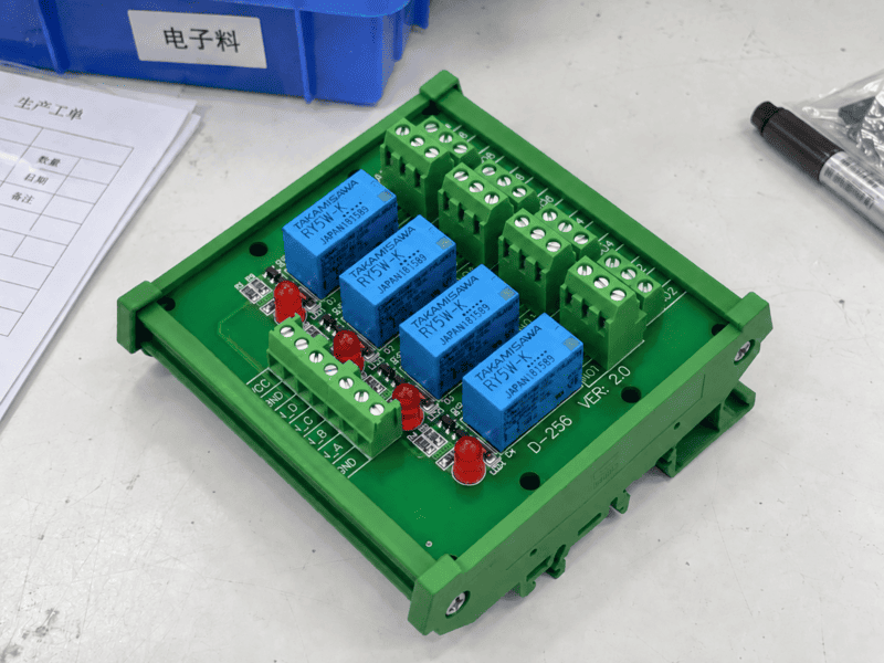
A passive PLC interface routes existing channels to accessible terminals, a relay interface switches or separates a field circuit, and a protected distribution module divides DC power into controlled branches. These external modules improve wiring, switching, isolation, or protection, but they do not create additional PLC I/O points.
Add the simultaneous current required by the PLC, I/O modules, interface electronics, and field devices, then check startup current, derating, voltage drop, protection, and the manufacturer’s design rules separately.
A power supply should not be selected from PLC wattage alone. The cabinet may also contain sensors, communication modules, HMI equipment, relay coils, valves, signal conditioners, and protected branch circuits.
AutomationDirect’s CLICK documentation provides a useful family-specific example: it lists logic-side PLC power and external field-side power separately, then instructs the designer to total the selected CPU and module currents and compare them with available supply capacity.11 The exact numbers apply to CLICK products, but the checking method is broadly useful.
| Load group | Quantity | Current per unit | Simultaneous current |
|---|---|---|---|
| PLC CPU and communication modules | As designed | From manufacturer data | Quantity × current |
| I/O and interface electronics | As designed | From module data | Quantity × current |
| Sensors and transmitters | Expected ON simultaneously | From device data | Quantity × current |
| Relay and contactor coils | Expected ON simultaneously | Holding current, with inrush checked separately | Quantity × holding current |
| Solenoid valves and indicators | Expected ON simultaneously | From load data | Quantity × current |
| HMI or auxiliary devices | As designed | From device data | Quantity × current |
Required continuous load current = sum of the loads expected to operate at the same time
This is the starting point, not the final power-supply rating.
There is no universal percentage margin that is correct for every panel. A fixed “add 20%” rule can still fail if the inrush profile or temperature derating is ignored, and it can oversize a supply without solving a distribution fault. Use the power-supply and PLC manufacturers’ sizing instructions for the actual system.
Suppose a preliminary design contains:
| Load | Simultaneous current |
|---|---|
| PLC CPU and I/O | 0.45 A |
| Eight sensors | 0.32 A |
| Interface relays energized together | 0.24 A |
| Four valves energized together | 1.20 A |
| HMI | 0.50 A |
| Calculated continuous demand | 2.71 A |
The designer should next compare 2.71 A with the candidate supply under the actual ambient condition, then check valve and relay inrush, wiring drop, branch ratings, protection, and planned expansion. This example is a calculation method, not a universal recommendation to choose one specific amperage.
The result can range from failure to turn on through intermittent resets and false signals to permanent damage or an electrical hazard.
| Error | Possible result | What to check |
|---|---|---|
| Voltage above the allowed range | Damaged CPU, I/O channel, sensor, or protection device | Actual measured voltage, transient conditions, supply setting |
| Voltage below the allowed range | Brownout, reset, communication loss, output dropout | Supply capacity, inrush, cable drop, loose terminals |
| AC applied to DC-only terminals | Immediate damage or unsafe failure | Terminal labels and model manual before energizing |
| Reversed DC polarity | No operation or damage if protection is absent/inadequate | +24 V, 0 V, polarity protection, connector pinout |
| Wrong PNP/NPN relationship | Input never turns on, stays on, or behaves unpredictably | Input common, sensor output type, sink/source diagram |
| Field supply missing | PLC runs but sensors or outputs do not work | Separate field fuses, breakers, disconnects, and commons |
| Load current above output rating | Output fault, overheating, welded relay contact, shortened life | Continuous current, inrush, duty cycle, load type, temperature |
| Uncoordinated grounding/common | Noise, ground-loop current, false readings | 0 V reference, protective earth, cable shield, isolation plan |
Do not repeatedly replace a PLC output fuse or module without finding the electrical cause. The real problem may be a shorted field cable, inductive transient, load inrush, incorrect common, or an output selected for the wrong load type.
Verify voltage from the exact CPU, I/O, and load documentation, then trace the complete current path on the drawing before connecting power.
At NITAI, we prefer to organize a PLC wiring review in the following order because it prevents the word “24 V” from hiding incompatible circuits:
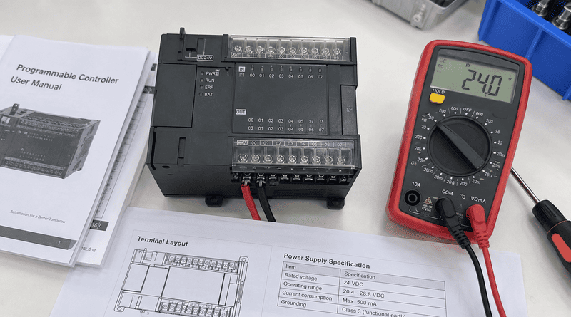
A reliable PLC voltage check brings the exact part number, manufacturer datasheets, terminal plan, power budget, and marked wiring diagram together. The review should separately identify controller supply, inputs, outputs and loads before any conductor is connected or an energized measurement is attempted.
The most common mistake is treating every “24 V” label as though it describes the same circuit.
| Mistake | Why it is wrong | Better approach |
|---|---|---|
| “All PLCs use 24 VDC.” | AC- and other DC-powered models exist. | Read the exact CPU supply specification. |
| “A 24 VDC CPU has only 24 V signals.” | Analog and special-purpose I/O use other signal ranges. | Check every module and channel type. |
| “The PLC output supplies 24 V automatically.” | Many outputs only switch an external supply. | Draw the complete load-current path. |
| “A relay output can switch anything.” | Contacts have voltage, current, load, inrush, and life limits. | Select from the contact-rating table for the actual load. |
| “0 V and earth are interchangeable.” | 0 V is a circuit reference; PE has a protective function. | Follow the system grounding and bonding design. |
| “If voltage matches, PNP/NPN does not matter.” | Current direction and input common determine compatibility. | Match source/sink behavior and terminal diagram. |
| “The internal 5 V value is a field-wiring voltage.” | Backplane power is generated and managed inside the system. | Apply power only to documented external terminals. |
| “Power-supply watts are enough.” | Voltage drop, inrush, channel limits, and protection may still fail. | Complete both the power budget and distribution review. |
| “A 0–10 V input powers a 10 V device.” | An input range describes measurement, not necessarily excitation power. | Determine who supplies the sensor or loop. |
A useful inquiry should identify the PLC, every signal type, the field loads, and the required wiring functions—not just the channel count.
| Information to provide | Example of a useful answer |
|---|---|
| PLC brand and full model | Manufacturer plus complete CPU catalog number |
| I/O module part numbers | Exact digital input, transistor output, relay output, or analog module |
| Controller supply | 24 VDC or 100–240 VAC, including allowed range |
| Digital input details | 24 VDC, PNP sensor, eight channels, common arrangement |
| Digital output details | Sourcing transistor output, six channels, current per load |
| Analog details | 0–10 V or 4–20 mA, active/passive loop, isolation required or not |
| Field-device list | Sensors, relay coils, valves, contactors, lamps, transmitters |
| Load voltage and current | Nominal value, continuous current, inrush, inductive/resistive load |
| Interface purpose | Terminal conversion, relay isolation, signal conversion, or distribution |
| Protection requirement | Individual fuse/breaker, disconnect, status indication |
| Connector and cable | PLC connector, field terminal type, conductor size, cable length |
| Installation conditions | DIN rail, panel space, temperature, vibration, environment |
| Wiring documents | PLC manual pages, field-device datasheets, marked schematic |
This information allows the electrical question to be checked before anyone discusses a terminal board, relay module, distribution module, or cable assembly. It also exposes contradictions early—for example, a 24 VDC transistor output being proposed for a 230 VAC coil.
The answers below are quick checks; the exact model manual still controls the final design.
Many industrial PLCs use 24 VDC, but 12 VDC variants exist and some CPUs accept AC mains. Read the full part number and supply-terminal rating.
It can use either. Some PLCs accept AC directly, while many use an external AC-to-24-VDC power supply. I/O and field-load circuits may still use different voltages.
It is a widely supported industrial control voltage across controllers, sensors, interfaces, relays, and actuators. That makes distribution and service practical, but compatibility still depends on detailed ratings.
Yes, through an appropriately rated relay output, interposing relay, solid-state device, or contactor arrangement. Do not connect 230 VAC to a DC transistor output. The switching device, protection, separation, and wiring must be designed for the actual load.
Usually not in the general sense. A transistor output switches an external DC circuit, a relay output switches an externally supplied circuit, and an analog output produces a limited control signal. Some controllers provide auxiliary power terminals, but their permitted use and current are model-specific.
No. Zero volts is the reference/return for a DC circuit, while protective earth is a safety conductor. A design may bond them at a defined point, keep them isolated, or manage them another way. Follow the manufacturer’s grounding instructions and applicable standards.
Sometimes, if the manuals allow it and the supply, protection, noise, voltage drop, commons, and isolation have been properly designed. Some systems benefit from separate logic and field supplies. AutomationDirect, for example, distinguishes logic-side and field-side power in its CLICK power documentation.
Only if the input specification recognizes the sensor’s output levels or a suitable signal-conditioning/interface device is used. A normal 24 VDC input may not treat 5 V as ON, and applying 24 V to a 5 V sensor can damage it.
No. The 0–10 V value describes the analog signal range. The PLC or module may be powered by 24 VDC or another specified supply.
The contact itself generally opens or closes an external circuit. It does not create the load voltage. The external supply and load are wired through contacts that must be rated for that voltage and load.
Electronic outputs can have leakage current, and meters with high input impedance can display a “ghost” voltage through suppression components or coupled wiring. Confirm the output specification and test under the manufacturer’s recommended conditions before assuming the output has failed.
Low voltage more commonly causes malfunction than immediate physical damage. It can produce resets, unstable communications, false behavior, or output dropout, so repeated brownouts should be investigated rather than treated as harmless.
No. IEC 61131-2 defines equipment requirements and tests for programmable controllers and associated peripherals. It does not mean every PLC uses one identical supply, input, or output voltage.
Most modern PLC systems commonly use 24 VDC, but the correct voltage can only be determined by separating controller power, internal/backplane power, input signals, output type, and field-load supply.
Before wiring, confirm the exact PLC and I/O part numbers, trace the current path, and check voltage range, current, polarity, source/sink behavior, isolation, protection, and load characteristics.
If you are planning a PLC interface or control-cabinet wiring project, send NITAI the PLC and I/O part numbers, field-device datasheets, channel count, voltage/current data, connector information, and proposed schematic. We can use those details to help organize the terminal, interface, relay, or DC distribution requirements before product selection.
**International standard scope:** [IEC 61131-2:2017 — Industrial-process measurement and control, programmable controllers, equipment requirements and tests](https://webstore.iec.ch/en/publication/31007). Supports the statement that PLC/PAC equipment and associated peripherals are covered by defined functional and EMC requirements. It does not prescribe one universal operating voltage for every PLC. ↩
**Manufacturer specification:** [OMRON CP1E CPU Units — General Specifications](https://www.ia.omron.com/products/family/2064/specification.html). Supports the comparison between 100–240 VAC CP1E supply models and 24 VDC supply models, including their model-specific operating ranges and inrush data. Values apply to the listed CP1E variants only. ↩
**Manufacturer selection guide:** [Rockwell Automation Micro800 Programmable Controller Family Selection Guide](https://literature.rockwellautomation.com/idc/groups/literature/documents/sg/2080-sg001_-en-p.pdf). Supports the distinction among controller power-supply options, input types, relay outputs, 24 VDC source/sink outputs, and 0–10 V analog channels in the Micro800 family. Availability depends on the exact catalog number. ↩
**Manufacturer product data:** [Siemens SIMATIC S7-1200 CPU 1212C DC/DC/DC, 6ES7212-1AE40-0XB0](https://sieportal.siemens.com/en-ww/products-services/detail/6ES7212-1AE40-0XB0?tree=CatalogTree). Supports the model-specific example of 20.4–28.8 VDC controller power, 24 VDC digital I/O, and 0–10 V analog inputs. It must not be generalized to all S7-1200 or other PLC models. ↩
**Manufacturer I/O-system guide:** [Rockwell Automation POINT I/O Modules Selection Guide](https://literature.rockwellautomation.com/idc/groups/literature/documents/sg/1734-sg001_-en-p.pdf). Supports the example in which incoming 24 VDC is converted to 5 VDC backplane power and documents separate field-side input/output ratings. These details apply to the specified POINT I/O products. ↩
**Manufacturer technical data:** [Rockwell Automation Micro800 Programmable Controllers Technical Data](https://literature.rockwellautomation.com/idc/groups/literature/documents/td/2080-td001_-en-p.pdf). Supports the use of detailed ON/OFF thresholds, input currents, analog ranges, output voltage/current limits, relay contact ratings, and temperature-dependent ratings. Always use the table for the exact controller or module. ↩
**Manufacturer analog-module example:** [Phoenix Contact AXL SE AI4 U 0-10 Analog Module, item 1088104](https://www.phoenixcontact.com/en-ae/products/io-component-axl-se-ai4-u-0-10-1088104). Supports the distinction between a 24 VDC module supply and a 0–10 V analog input range. These values are specific to that module. ↩
**Manufacturer relay principle:** [OMRON Overview of General Purpose Relays](https://www.ia.omron.com/support/guide/36/introduction.html). Supports the explanation that energizing a relay coil moves contacts between NC and NO states. Actual PLC relay-output ratings must still be taken from the PLC manufacturer. ↩
**Manufacturer interface overview:** [Weidmüller PLC Interfaces and Pre-Assembled Cables](https://www.weidmueller.com/int/products/connectivity/plc_interfaces_and_migration_solutions/plc_interfaces_passive.jsp). Supports the distinction between passive/active PLC interfaces and functions such as fuses, disconnectors, and relay isolation. Product capability depends on the selected module. ↩
**Manufacturer protection example:** [Phoenix Contact Electronic Circuit Breakers](https://www.phoenixcontact.com/en-pc/products/device-circuit-breakers/electronic-circuit-breakers). Supports the example of multi-channel protection for 24 VDC loads against overload and short circuit. It does not mean every distribution block includes electronic protection. ↩
**Manufacturer power-budget example:** [AutomationDirect CLICK Power Considerations](https://www.automationdirect.com/clickplcs/getting-started/power-considerations). Supports separating logic-side PLC power from external field-side power and totaling the current demand of the selected CPU, modules, and field devices. Numerical values and separation recommendations on the page are specific to CLICK systems. ↩

Choosing an M12 connector manufacturer is not simply a matter of selecting the best-known name. The right supplier…
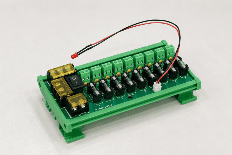
A complete 12V power supply box is not simply a 12V power adapter. It normally combines an AC-to-DC…
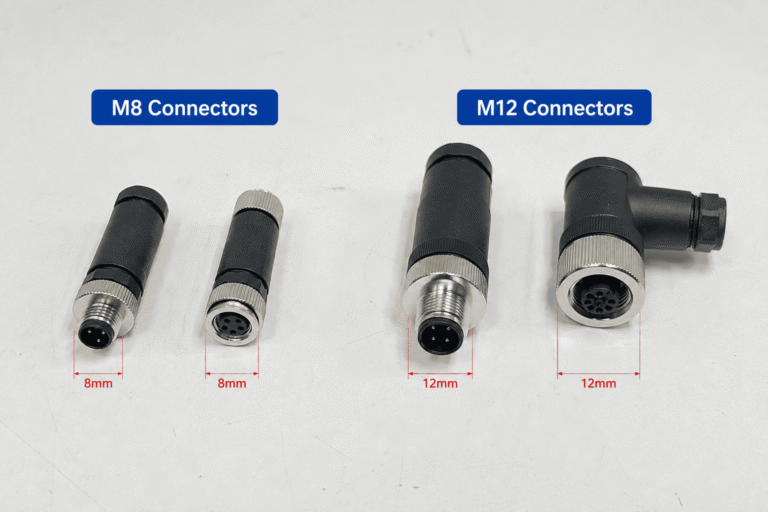
M8 and M12 connectors both appear throughout industrial automation, but they are not interchangeable drop-in options. Choose M8…
NITAI manufactures terminal blocks, M8/M12 waterproof connectors and industrial distribution modules for global OEMs, distributors and automation customers.
Leave a Reply