Oct 17, 2026
How Do I Choose the Right M8 8 Pin Female Connector for My Equipment?
An M8 8 pin female connector can look like the right replacement on a purchasing list and still…

The name distribution box is used for products ranging from a small breaker enclosure to a large industrial power-distribution assembly. That makes the initial inquiry sound simpler than it really is. Two boxes may have the same number of visible outgoing ways but differ completely in voltage, phase arrangement, fault rating, protective devices, enclosure performance, and intended users.
A distribution box is an enclosed electrical assembly that receives an incoming supply and divides it into multiple outgoing circuits. Depending on its design, it may include a main isolator or breaker, busbars, branch circuit breakers or fuses, neutral and protective-earth terminals, surge or residual-current protection, metering, and connection terminals. The correct box must be selected from the electrical system and protection requirements—not from its size or number of ways alone.
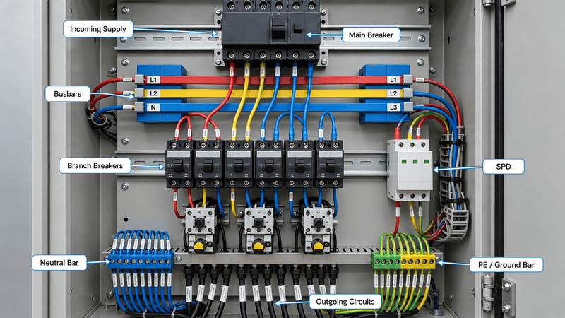
A complete distribution box combines an enclosure with incoming isolation, internal power distribution, branch protection, conductor connections, and clearly identified outgoing circuits.
When customers ask us about terminal blocks or power-distribution components for a box, I first ask for the one-line diagram or wiring schematic. A photograph can show the enclosure and installed devices, but it cannot confirm the current path, prospective fault level, internal commoning, or protection assigned to each outgoing circuit.
An electrical distribution box is the point at which one incoming electrical supply is divided into several outgoing circuits or loads, normally with a defined means of isolation and circuit protection.
The expression may overlap with distribution board, breaker box, panelboard, or electrical panel. The preferred term varies by region, system size, application, and product standard. For that reason, I use the internal electrical function—not the marketing name—as the starting point.
IEC 61439-1:2020 establishes general definitions, service conditions, construction requirements, technical characteristics, and verification requirements for low-voltage switchgear and controlgear assemblies1. The applicable product-specific part still depends on who will operate the assembly and where it is used.
For example, IEC 61439-3:2024 covers distribution boards intended to be operated by ordinary persons and describes assemblies containing outgoing circuits with protective devices2. Industrial power switchgear and controlgear assemblies may instead fall within IEC 61439-2:20203. A product advertised simply as a “distribution box” is therefore not automatically suitable for every residential, commercial, or industrial installation.
| Basic Function | What It Means in Practice |
|---|---|
| Receive the supply | Accept power from an upstream board, transformer, power supply, generator, or other defined source |
| Provide isolation | Allow the complete box or selected circuits to be disconnected where the design requires it |
| Distribute power | Route the incoming conductors or busbars to multiple outgoing protective devices and circuits |
| Protect circuits | Use appropriate breakers, fuses, residual-current devices, or other protection according to the system design |
| Organize connections | Provide identified phase, neutral, PE, control, and outgoing conductor terminations |
| Protect internal parts | Use an enclosure suitable for the installation environment and access conditions |
The enclosure alone is not the complete distribution system. The internal devices, conductors, busbars, terminals, clearances, protective coordination, and assembled performance are all part of the engineering decision.
A distribution box routes the incoming supply through isolation and distribution components, then sends it through individual protective devices to separate outgoing circuits. A fault in one correctly designed branch can be disconnected without necessarily removing power from every other branch.
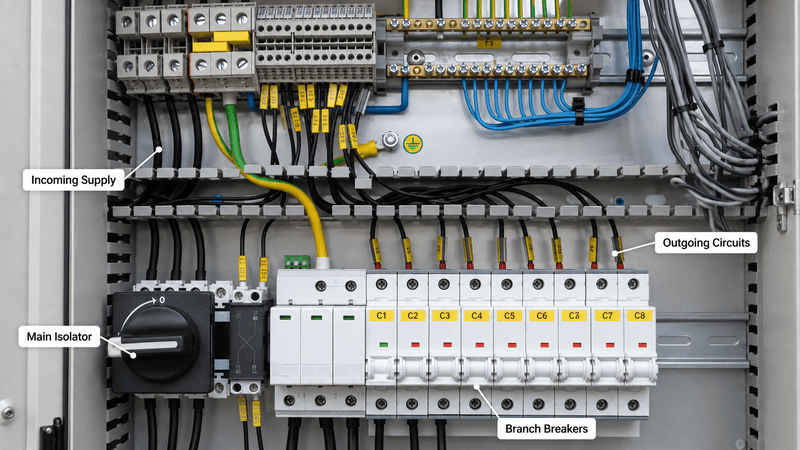
The basic power path is incoming supply, main isolation or protection, internal bus distribution, branch protection, and separately identified outgoing circuits.
A simplified sequence is:
Incoming supply → main switch or breaker → busbar or distribution system → branch protective device → outgoing circuit → load
The neutral and protective-earth paths must be designed separately from the live-conductor path. Their arrangement depends on the earthing system, supply, application, and local installation rules; neutral, PE, and DC 0 V should never be treated as interchangeable labels.
| Stage | Typical Role | What Must Be Confirmed |
|---|---|---|
| Incoming cable or bus | Brings power into the box | AC/DC, voltage, phase, frequency, conductor size, source protection |
| Main switch or breaker | Isolates or protects the incoming supply | Number of poles, rating, isolation function, fault capability |
| Busbar or power-distribution path | Feeds several outgoing devices | Rated current, temperature rise, phase arrangement, short-circuit withstand |
| Branch breaker or fuse | Protects an outgoing circuit | Load current, conductor size, trip characteristic, breaking capacity |
| Neutral terminal or bar | Connects circuit neutrals where required | Earthing system, conductor sizing, separation, identification |
| PE terminal or bar | Connects protective conductors | Bonding method, conductor capacity, mechanical continuity |
| Outgoing terminal or cable | Supplies the downstream load | Load type, inrush, voltage drop, cable entry, identification |
The exact sequence may differ. Some assemblies have an upstream main protective device located elsewhere; some use fused switches, molded-case breakers, miniature circuit breakers, or electronic protection; and some contain monitoring and control functions in addition to power distribution.
The common components are an enclosure, incoming isolation or protection, busbars or distribution conductors, branch protective devices, neutral and PE terminals, outgoing terminals, internal wiring, cable entries, and identification. Additional devices depend on the installation.
Schneider Electric's Electrical Installation Guide treats circuit breakers, residual-current devices, surge protection, conductor sizing, and electrical-distribution design as coordinated parts of an installation rather than isolated product choices4. That system view is important: adding a high-rated breaker does not automatically raise the rating of the busbar, terminals, conductors, enclosure, or complete assembly.
| Component | Primary Function | Selection Question |
|---|---|---|
| Enclosure | Prevents unintended contact and protects installed equipment from specified environmental conditions | Indoor or outdoor? Dust, water, corrosion, impact, access, and temperature conditions? |
| Main isolator | Disconnects the complete assembly from the incoming supply | Is visible isolation, locking, or multi-pole disconnection required? |
| Main circuit breaker or fuse | Provides upstream overcurrent protection where included | What are the load current and prospective short-circuit current? |
| Busbar | Distributes one or more phases or poles to outgoing devices | What continuous current, temperature rise, fault withstand, and spacing apply? |
| MCB, MCCB, or branch fuse | Protects each outgoing circuit against defined overcurrent conditions | What conductor, load, trip curve, breaking capacity, and coordination are required? |
| RCD, RCCB, or RCBO | Provides residual-current protection where required | What system, circuit, sensitivity, selectivity, and local rules apply? |
| Surge protective device | Limits transient overvoltage where required by the design | What supply system, exposure, SPD type, backup protection, and coordination apply? |
| Neutral bar or terminals | Connects neutral conductors | Is the neutral switched, protected, separated, or fully rated for the load? |
| PE bar or PE terminals | Provides protective-conductor connections | How is the enclosure bonded, and how is PE continuity maintained? |
| Terminal blocks | Create accessible and identified conductor interfaces | What wire range, current, voltage, terminal technology, and mounting method apply? |
| Metering or monitoring | Measures current, voltage, energy, status, or alarms | What accuracy, communication, sensors, and auxiliary supply are required? |
| DIN rail and mounting plate | Supports installed devices | What device spacing, wiring duct, service access, and mechanical loading apply? |
| Cable glands or entry system | Routes cables while maintaining strain relief and environmental protection | What cable diameters, sealing level, EMC treatment, and entry direction apply? |
Not every distribution box contains every item in this table. A small final distribution board may be relatively simple, while an industrial assembly may require larger protective devices, monitoring, control power, ventilation, segregated sections, and detailed documentation.
Distribution boxes can be classified by their position in the electrical system, power configuration, application, installation environment, and form of use. These classifications are more useful than treating every enclosure with a different accessory as a separate “type.”
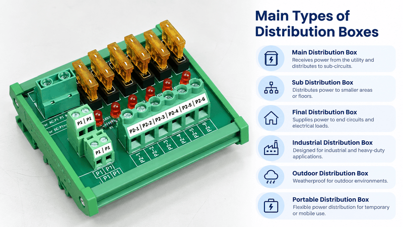
A distribution box may be classified by where it sits in the system, what loads it supplies, and the environment in which it operates.
| Type or Classification | Typical Position or Use | Main Selection Focus |
|---|---|---|
| Main Distribution Board (MDB) | Receives a main low-voltage supply and feeds sub-boards or major loads | High incoming current, fault level, metering, outgoing feeders, maintainability |
| Sub Distribution Board (SDB) | Receives power from an MDB and supplies one zone, floor, production area, or group of loads | Feeder protection, local isolation, circuit count, discrimination with upstream devices |
| Final Distribution Board | Supplies final lighting, socket, equipment, or small-load circuits | Branch protection, user access, residual-current requirements, labeling |
| Industrial Distribution Box | Supplies machinery, process areas, auxiliary systems, or industrial loads | Load types, inrush, fault current, environment, monitoring, skilled-person access |
| Outdoor Distribution Box | Installed where rain, dust, sunlight, temperature, corrosion, or condensation must be considered | Complete enclosure rating, glands, seals, drainage, material, thermal design |
| Portable or Temporary Distribution Box | Used for maintenance, construction, events, or temporary equipment | Mechanical durability, plugs and sockets, cable protection, earthing, RCD requirements |
| Single-Phase Distribution Box | Distributes a single-phase supply | Pole arrangement, neutral, total load, circuit balance where relevant |
| Three-Phase Distribution Box | Distributes three-phase and possibly single-phase outgoing circuits | Phase sequence, load balance, neutral current, pole configuration, fault level |
| AC Distribution Box | Distributes an alternating-current supply | Frequency, voltage, switching category, protection and conductor arrangement |
| DC Distribution Box | Distributes a direct-current supply | Polarity, DC-rated switching/protection, voltage, current direction, arc interruption |
These terms are not perfectly standardized across every country. The words main, sub, and final describe system hierarchy; outdoor describes the environment; and single-phase, three-phase, AC, and DC describe the electrical system. One physical product may fit several descriptions at the same time.
The key difference is function. A distribution box supplies several circuits and normally includes circuit-level isolation or protection; a terminal box or junction box mainly provides connection space; a distribution block or module distributes conductors or potentials but does not automatically perform the functions of a complete protected assembly.
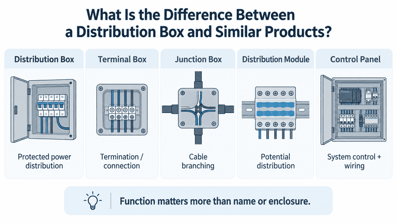
Products with similar enclosures can serve very different electrical functions, so the internal circuit and protection arrangement matter more than the name.
| Product | Main Purpose | Branch Protection Normally Included? | Enclosure Normally Included? |
|---|---|---|---|
| Distribution box or board | Divide an incoming supply into multiple outgoing circuits | Usually, but verify the exact assembly | Yes |
| Empty electrical enclosure | House and protect components selected by the builder | No | Yes |
| Junction box | Contain conductor joints or branches | No, unless specifically designed otherwise | Yes |
| Terminal box | Provide organized conductor terminations | No, unless specifically designed otherwise | Yes |
| Power distribution block | Split one conductor or potential into several connection points | No | No |
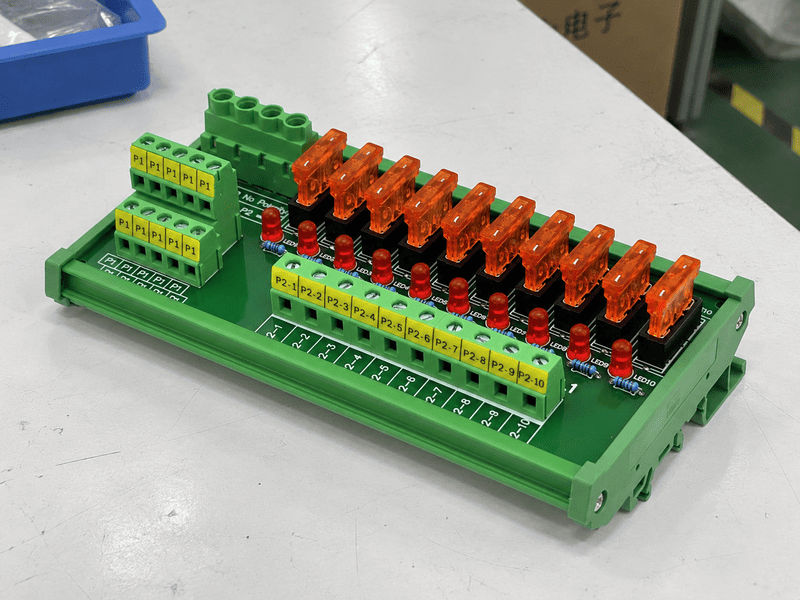
| Fused distribution module | Distribute power with product-specific branch fuses | Fuse protection may be included | Usually installed inside another enclosure |
| Control panel | Control a machine or process using power and control devices | Depends on the panel design | Yes |
| Switchgear assembly | Switch, protect, control, and isolate electrical power at a defined system level | Yes, according to its design | Usually |
Our detailed guide to a terminal distribution box explains the naming problem from the connection side. This article uses distribution box for the higher-level assembly that distributes protected outgoing circuits.
There is no universal protection package for every distribution box. The required devices depend on the supply system, available fault current, conductor sizes, load characteristics, earthing arrangement, users, environment, and applicable local rules.
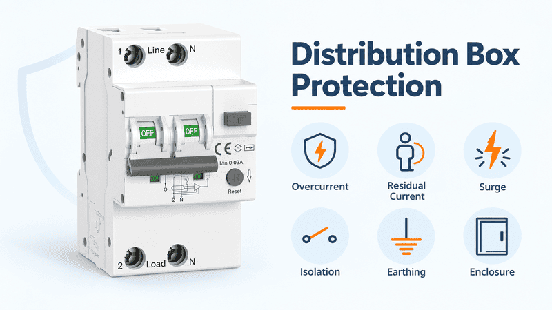
A reliable distribution design considers several different hazards; one protective device cannot replace every other protection function.
| Protection Function | Typical Device or Design Feature | What It Addresses |
|---|---|---|
| Overload protection | Circuit breaker or fuse | Current above the conductor or circuit's continuous capacity |
| Short-circuit protection | Circuit breaker or fuse with adequate breaking capability | High fault current and associated thermal or mechanical stress |
| Residual-current protection | RCD, RCCB, or RCBO where required | Earth-leakage or residual-current conditions |
| Surge protection | Coordinated SPD system where required | Transient overvoltage from lightning or switching events |
| Isolation | Isolator, switch-disconnector, or suitable breaker | Safe disconnection for operation or maintenance |
| Protective bonding | PE conductors, terminals, and enclosure bonding | Fault-current path and accessible conductive parts |
| Ingress protection | Tested enclosure, doors, seals, glands, and entries | Contact, solid objects, dust, and water according to the claimed IP code |
| Thermal protection | Correct loading, spacing, ventilation, cooling, or temperature monitoring | Excessive internal temperature and component derating |
The current rating printed on a breaker is not its complete short-circuit specification. IEC 60947-2:2024 covers circuit breakers intended for low-voltage circuits and operated by instructed or skilled persons5. The selected device and assembly must be suitable for the prospective short-circuit current at the installation point.
The Schneider Electric installation guide explains that a circuit breaker's breaking rating is the highest prospective fault current it can interrupt under its specified conditions. A box should therefore not be selected only from normal load current; the fault level and protective-device capability must also be checked.
For North American industrial equipment, short-circuit current rating is commonly expressed as SCCR. Eaton notes that equipment should not be installed where the available fault current exceeds its marked SCCR6. This terminology and the applicable rules are market-specific, so an IEC rating and a North American SCCR marking should not be treated as interchangeable without review.
No. IEC 60529 classifies the protection provided by enclosures against access, solid objects, dust, and water7. It does not replace overload, short-circuit, shock, thermal, or application-specific protection.
The claimed IP degree must apply to the complete assembled condition, including doors, covers, cable glands, blanking plugs, seals, and operating devices. A bare internal module does not inherit the enclosure's IP rating when it is removed from that enclosure.
Start with the system diagram, supply, loads, fault level, and protection concept. Only after those are defined should you select the enclosure size, number of ways, terminal arrangement, and accessories.
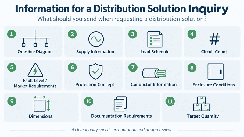
The selection process moves from the electrical system and fault conditions to circuits, conductors, enclosure, layout, documentation, and future expansion.
Confirm whether the box is the main board, a downstream sub-board, a machine distribution assembly, a final-circuit board, or a temporary power unit. Identify the upstream source and every downstream load or board.
A one-line diagram is more useful than a product photograph because it shows how the box interacts with the rest of the electrical system.
Record:
A DC breaker or switch must be suitable for the required DC voltage and polarity arrangement. AC ratings should not be applied to a DC circuit without explicit manufacturer documentation.
List every outgoing circuit, connected load, normal current, starting or inrush current, duty cycle, conductor, and required protective function. Motors, transformers, power supplies, lamps, heaters, capacitive loads, and electronic equipment can impose very different starting and fault conditions.
I do not calculate a distribution box from the sum of nameplate currents alone. Simultaneous loading, diversity, phase balance, harmonics, future circuits, temperature, and manufacturer derating may all affect the design.
The designer must determine the prospective short-circuit current at the intended installation point and verify that the assembly and protective devices have adequate fault withstand and interruption capability.
In practical terms, the required breaking capacity must be checked at the location where the device will be installed—not copied from another panel elsewhere in the system.
Confirm the main protection, branch protection, residual-current protection, surge protection, and isolation requirements. Coordination should consider both fault clearing and continuity: the desired result is normally to disconnect the affected branch without unnecessarily removing power from unaffected circuits.
This cannot be determined from the number of breakers alone. Device curves, settings, upstream/downstream combinations, load characteristics, and the manufacturer's coordination data may be required.
Schneider Electric's conductor-sizing methodology requires the cabling and protection to carry full load and normal short-time overcurrents without unacceptable voltage drop8. Installation method, conductor material, insulation, ambient temperature, grouping, harmonics, voltage drop, and short-circuit withstand can affect the required cross-section.
Check the complete current path:
The rating of the most visible component is not automatically the rating of the complete path.
Confirm indoor or outdoor use, dust, water, oil, corrosion, UV exposure, ambient temperature, condensation, impact, cleaning, hazardous-area requirements, and who can access the box.
Metal and polymer enclosures each have possible advantages, but material alone does not determine suitability. Bonding, corrosion resistance, flame performance, impact resistance, sealing, cable entries, and thermal behavior must be evaluated for the actual installation.
Allow space for wiring bends, cable ducts, labels, terminal access, replacement of protective devices, test points, and future circuits. Dense packaging may make a box smaller while increasing wiring difficulty and internal temperature.
Rittal explains that enclosure climate-control selection depends on the total heat dissipated by installed components, ambient temperature, and the enclosure's thermal properties9. Thermal design should therefore be based on component losses and operating conditions rather than enclosure dimensions alone.
Before purchasing, verify the one-line diagram, schematic, general arrangement drawing, device schedule, terminal plan, ratings, labels, bill of materials, installation instructions, and required verification documents.
IEC TR 61439-0:2022 provides guidance from the specifier's perspective on defining the functions and characteristics needed for a low-voltage assembly10. That is a useful reminder that the buyer and assembly manufacturer need an agreed technical specification, not only a box size and circuit count.
| Selection Item | Information to Confirm | Why It Changes the Design |
|---|---|---|
| System position | Main, sub, final, machine, temporary, or auxiliary distribution | Determines upstream/downstream relationships and responsibilities |
| Supply | AC/DC, voltage, phase, frequency, poles, earthing system | Determines device, insulation, conductor, and protection arrangement |
| Loads | Type, normal current, inrush, duty, simultaneity | Determines current path, protection, temperature, and capacity |
| Fault level | Prospective short-circuit current or applicable SCCR requirement | Determines breaking and withstand capability |
| Outgoing circuits | Quantity, ratings, load groups, spare ways | Determines internal layout and protective-device count |
| Conductors | Material, cross-section, installation, length, entries | Affects ampacity, voltage drop, terminals, and gland layout |
| Environment | Indoor/outdoor, dust, water, corrosion, heat, condensation | Determines enclosure, sealing, material, and thermal control |
| Access | Ordinary, instructed, or skilled persons | Affects the applicable product concept and protective measures |
| Documentation | Drawings, labels, datasheets, verification, market requirements | Confirms what is actually supplied and approved |
Terminal blocks and distribution modules create organized connection and potential-distribution points inside a box. They simplify wiring, but they do not automatically replace the assembly's main isolator, branch breakers, fault rating, enclosure, or verification.
Internal connection components can organize incoming, outgoing, neutral, PE, and auxiliary circuits while the complete distribution box provides the required system-level protection and enclosure.
Phoenix Contact describes distribution blocks with integrated bridging that distribute one potential across several connection points11. This is a good example of component-level distribution: the block provides an organized current path, but its function is not the same as a complete breaker-equipped distribution box.
| Internal Component | Useful Function | Important Limitation |
|---|---|---|
| Feed-through terminal block | Creates an accessible incoming or outgoing conductor interface | Does not create branch protection by itself |
| PE terminal | Connects a protective conductor to the designated mounting/bonding system | Must be used within the intended PE arrangement |
| Neutral terminal or disconnect terminal | Organizes neutral conductors and may support testing or isolation | Neutral treatment depends on the electrical system |
| Distribution block | Splits one conductor or potential into several outputs | Total and branch current paths must be checked |
| Fused distribution module | Adds product-specific fuse protection to several branches | Fuse type, voltage, current, fault capability, and upstream protection still matter |
| Switched distribution module | Adds manual branch switching | A switch is not automatically a protective device |
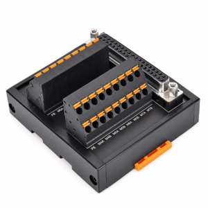
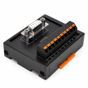
| Interface module | Converts a connector or cable interface into accessible terminals | Intended for organized connection, not mains branch protection unless specifically designed |
At NITAI, the relevant products are internal connection and distribution components used in control-cabinet and equipment wiring. You can review our Distribution & Interface Modules and terminal block range. We should not describe one of these internal components as a complete distribution box unless the enclosure, protection, ratings, and full assembly have actually been defined.
Send the one-line diagram, supply information, load schedule, circuit count, fault-level or market requirements, protective-device concept, conductor information, enclosure conditions, dimensions, documentation requirements, and target quantity.
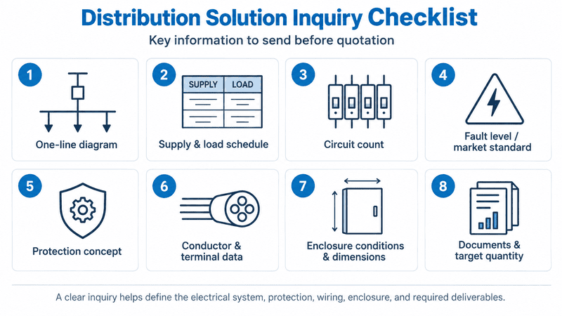
A useful inquiry defines the electrical system, protection, wiring, enclosure, documentation, and exact components that the supplier is expected to provide.
When customers send us only a photograph and ask for “the same distribution box,” I separate confirmed information from assumptions. The photograph may identify terminal style, DIN-rail layout, enclosure material, or the number of installed devices, but I still need the schematic and ratings before evaluating the terminal or distribution components.
| Information to Provide | Example of a Useful Answer |
|---|---|
| Required scope | Complete assembly, empty enclosure, terminal kit, or internal distribution module |
| System role | Sub-distribution box for one machine line |
| Supply | 400 V AC, three-phase, neutral and PE distributed |
| Upstream source | Supplied from an identified upstream board and protective device |
| Outgoing circuits | Quantity and individual circuit schedule |
| Load details | Load type, normal current, inrush, and duty for each circuit |
| Fault requirement | Prospective short-circuit current or required market-specific SCCR |
| Main device | Required isolation and incoming protection arrangement |
| Branch protection | Breaker, fuse, residual-current, and surge requirements |
| Conductors | Material, cross-section, cable diameter, entry direction, ferrule or lug requirements |
| Enclosure | Indoor/outdoor, material, required IP, dimensions, access, mounting |
| Internal layout | DIN rail, busbar, wiring duct, terminal numbering, spare capacity |
| Documentation | One-line diagram, schematic, GA drawing, terminal plan, labels, test or verification documents |
| Commercial information | Sample requirement, project quantity, annual demand, destination market |
For a replacement project, also provide clear front, side, interior, label, terminal, and cable-entry photographs. An existing model number, datasheet, drawing, or physical sample can help identify the mechanical construction, but the electrical specification should still be confirmed independently.
The most common mistakes are selecting by enclosure size or number of ways, ignoring fault current, assuming every internal component shares the same rating, treating IP as complete electrical protection, and failing to define what the supplier must include.
| Mistake | Why It Creates Risk | Better Check |
|---|---|---|
| Buying an empty enclosure as if it were a complete distribution box | It may contain no isolation, busbar, protection, terminals, or internal wiring | Define the supply scope and bill of materials |
| Selecting only by “8-way” or “12-way” | Way count does not define voltage, phase, current, pole arrangement, or protection | Provide a circuit schedule and one-line diagram |
| Checking normal current but not fault current | A device may carry the load but be unable to interrupt the available fault current | Verify prospective fault current and breaking/withstand ratings |
| Using one component rating as the assembly rating | Terminals, busbars, breakers, wiring, and enclosure may have different limits | Evaluate the complete current path and assembled design |
| Assuming every box needs the same RCD or SPD arrangement | Protection depends on the system, installation, risk, and local rules | Complete the protection study for the actual project |
| Treating IP65 or IP67 as an electrical safety certificate | IP addresses enclosure ingress/access performance, not all electrical hazards | Verify electrical protection and assembly documentation separately |
| Ignoring cable entries and door devices | Openings can affect sealing, spacing, strain relief, and maintainability | Review the complete assembled enclosure |
| Filling every available space | Dense wiring can make service difficult and increase thermal problems | Reserve wiring, heat-dissipation, and expansion space |
| Confusing PE, neutral, DC 0 V, and shield terminals | These conductors serve different system and safety functions | Follow the defined grounding, bonding, and EMC design |
| Ordering from photographs alone | Internal ratings and connections may not be visible | Obtain drawings, schedules, ratings, and verification records |
A distribution box is unnecessary when the project only needs a protected location for a splice, a set of organized terminations, or compact potential distribution inside an existing cabinet. It is also insufficient when the project requires a more complex control panel or switchgear assembly.
Consider another product direction when:
Choosing the narrower product when it meets the actual function can reduce space and wiring complexity. Choosing it when system-level isolation and protection are required creates the opposite result.
The terms often overlap, but usage varies by region and system size. Distribution board commonly refers to the organized assembly of busbars and protective devices, while distribution box may emphasize a smaller enclosed form. The internal function and applicable documentation matter more than the label.
No. Some use fuses, fused switches, electronic protection, or an upstream protective device. Products sold as empty distribution boxes may contain no electrical devices at all, so the exact supply scope must be checked.
Only when the complete design, devices, separation, insulation, identification, terminals, and protection are suitable for both systems. Do not assume that an AC-rated breaker, switch, or terminal arrangement is acceptable for DC.
It usually describes space or positions for eight outgoing protective devices or circuits, but manufacturers use the term differently. It does not define pole count, current, phase arrangement, spare capacity, or whether every position is populated.
Not when the system requires a complete enclosure, main isolation, branch circuit protection, fault rating, and assembly documentation. A module is normally one internal component of a larger electrical system.
There is no single rating suitable for every outdoor installation. Rain direction, dust, water jets, temporary immersion, condensation, UV, corrosion, cable entries, mounting, and local requirements must be assessed before selecting the complete enclosure.
Spare ways and physical space should reflect the project's realistic expansion plan, heat load, wiring access, and maintenance needs. A fixed percentage should not be applied blindly to every assembly.
A distribution box receives an incoming electrical supply and divides it into multiple outgoing circuits using an enclosure, internal distribution path, connection points, and the isolation or protective devices required by the design. Its suitability depends on the complete electrical system—not simply the box dimensions or number of ways.
Before selecting one, confirm the system position, AC/DC supply, voltage, phase, loads, simultaneous and inrush current, fault level, outgoing circuits, protection, conductor sizes, enclosure environment, access conditions, thermal design, spare capacity, applicable market requirements, and required documentation.
NITAI supplies terminal blocks and supports industrial distribution and interface module projects used inside control cabinets and equipment. Send us your one-line diagram, terminal plan, voltage, current, circuit relationship, conductor information, dimensions, photographs, target quantity, and destination market through our contact page. We can review the internal connection and distribution requirements before quotation or sampling.
IEC, [IEC 61439-1:2020 — Low-voltage switchgear and controlgear assemblies, Part 1: General rules](https://webstore.iec.ch/en/publication/32338). The official scope covers general definitions, service conditions, construction requirements, technical characteristics, and verification requirements for low-voltage assemblies. It is used together with the relevant product-specific part of the IEC 61439 series. ↩
IEC, [IEC 61439-3:2024 — Distribution boards intended to be operated by ordinary persons](https://webstore.iec.ch/en/publication/68496). The official scope describes DBO assemblies and outgoing circuits containing protective devices. It does not mean every product marketed as a distribution box falls within this part. ↩
IEC, [IEC 61439-2:2020 — Power switchgear and controlgear assemblies](https://webstore.iec.ch/en/publication/30043). This part defines specific requirements for power switchgear and controlgear assemblies within its voltage and frequency scope. The applicable standard still depends on the actual assembly and market. ↩
Schneider Electric, [Electrical Installation Guide](https://www.se.com/uk/en/work/products/product-launch/electrical-installation-guide/). This official professional guide covers the coordinated design of low-voltage installations, including protective devices, conductors, and distribution. Product and installation decisions must still follow the applicable local rules and exact manufacturer data. ↩
IEC, [IEC 60947-2:2024 — Low-voltage switchgear and controlgear, Part 2: Circuit-breakers](https://webstore.iec.ch/en/publication/66277). The standard applies to specified low-voltage circuit breakers intended for operation by instructed or skilled persons. Household or ordinary-person applications can involve other product standards. ↩
Eaton, [Short-Circuit Current Ratings](https://www.eaton.com/us/en-us/products/electrical-circuit-protection/fuses/short-circuit-current-ratings.html). Eaton explains the North American requirement that equipment not be installed where available fault current exceeds its marked SCCR. SCCR terminology and marking requirements should be applied only in the appropriate market and product context. ↩
IEC, [IEC 60529 consolidated version — Degrees of protection provided by enclosures (IP Code)](https://webstore.iec.ch/en/publication/2452). This standard classifies enclosure protection against access and ingress of solid objects and water. An IP code does not by itself establish overload, short-circuit, shock, thermal, or complete-assembly suitability. ↩
Schneider Electric Electrical Installation Guide, [Conductor sizing: methodology and definition](https://www.electrical-installation.org/enwiki/Conductor_sizing%3A_methodology_and_definition). The guide explains that conductors and protection must carry load and short-time overcurrent without unacceptable voltage drop. Final sizing depends on the applicable installation standard and project conditions. ↩
Rittal, [Industrial Enclosure Solutions: A Buying Guide for Panel Builders, Machine Builders, and System Integrators](https://www.rittal.com/us-en_US/Company/Rittal-Stories/Industrial-Enclosure-Solutions-A-Buying-Guide-for-Panel-Builders-Machine-Builders-System-Integrators). Rittal explains that enclosure heat load depends on installed-component dissipation, ambient temperature, and enclosure thermal properties. Exact cooling requirements must be calculated for the real assembly. ↩
IEC, [IEC TR 61439-0:2022 — Guidance to specifying assemblies](https://webstore.iec.ch/en/publication/66003). This technical report helps specifiers define the functions and characteristics required from a low-voltage assembly. It is guidance and does not replace the applicable product standard or verified design. ↩
Phoenix Contact, [Distribution blocks and device terminal blocks](https://www.phoenixcontact.com/en-in/products/distribution-blocks). This official product overview explains integrated bridging and single-potential distribution across multiple terminal points. The cited component function should not be confused with the function or rating of a complete distribution box. ↩
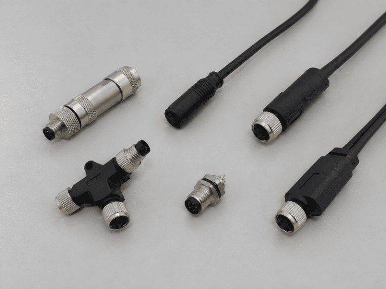
An M8 8 pin female connector can look like the right replacement on a purchasing list and still…
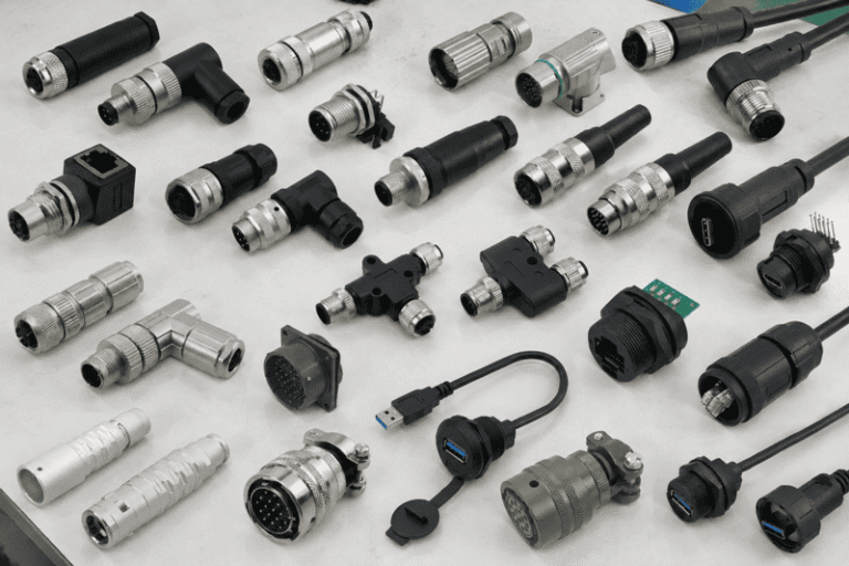
Connector types can look interchangeable in a catalog, but a familiar shape does not tell me whether two…
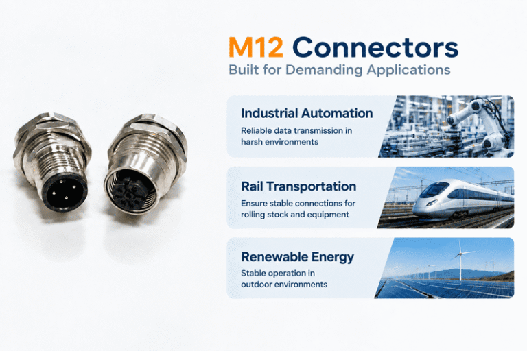
A coded and B coded M12 connectors can look similar in a purchasing list, but choosing the wrong…
NITAI manufactures terminal blocks, M8/M12 waterproof connectors and industrial distribution modules for global OEMs, distributors and automation customers.
Leave a Reply