Oct 16, 2026
What Is an M12 Male Connector 5-Pin B-Coded?
An M12 male connector 5-pin B-coded may look like a straightforward line item, but its name does not…

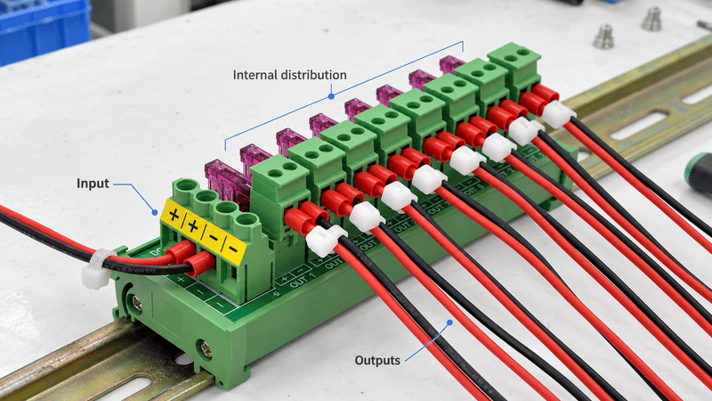
A terminal distribution box is an electrical connection assembly that organizes incoming conductors and distributes one or more electrical potentials to multiple outgoing terminals. Depending on the product, it may be an enclosure containing terminal blocks, a compact DIN-rail distribution block, a fused power distribution module, or a breaker-equipped distribution box. The name alone does not confirm the internal circuit or whether branch protection is included.
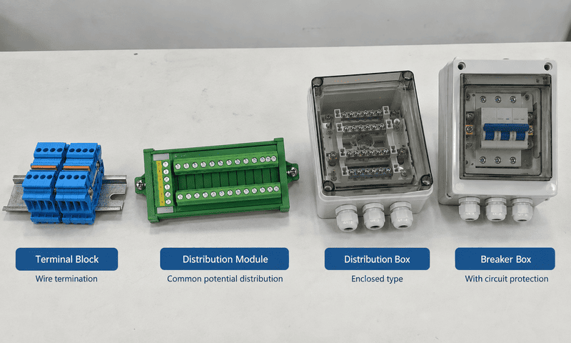
A product described as a terminal distribution box may provide simple wire termination, common-potential distribution, protected branch distribution, or a complete enclosed power-distribution function. The internal wiring diagram is more important than the product name.
Hi, I am Penny from NITAI. I support overseas product inquiries, specification clarification, and quotations for terminal blocks and industrial distribution and interface modules.
When I review an inquiry described only as a “terminal distribution box,” I do not select a product from that phrase alone. I first check whether the customer needs an empty enclosure, terminal blocks for organized wiring, one supply distributed to several outputs, or individually protected and switched branches. These products can look similar in a photograph but perform different electrical functions.
This guide explains the main meanings of terminal distribution box, how it differs from a terminal box, junction box, distribution terminal block, and breaker distribution box, and what information should be confirmed before selecting or requesting a quotation.
In industrial control-panel work, a terminal distribution box normally means an enclosure or module in which incoming power or conductors are terminated and then routed or distributed to multiple outgoing connections. However, the phrase is used inconsistently, so it should be treated as a starting description rather than a complete technical specification.
A typical industrial distribution arrangement contains an incoming connection, an internal conductive path or bus, and several outgoing terminals. Fuses, switches, LEDs, or circuit breakers are additional functions and should not be assumed.
IEC 60947-7-1 describes terminal blocks as components with screw-type or screwless clamping units that provide electrical and mechanical connections between copper conductors in industrial or similar applications.1 This helps explain the terminal part of the name, but it does not mean that every terminal assembly distributes one input to several outputs.
In supplier catalogs and project inquiries, the phrase may describe several different constructions:
| Possible Meaning | What Is Inside | Main Function | Protection Normally Included? |
|---|---|---|---|
| Enclosed terminal box | Enclosure, DIN rail, terminal blocks, cable entries | Organizes and protects wire terminations | No |
| Junction or connecting box | Splices, connectors, or terminal blocks | Joins or branches conductors | No |
| Distribution terminal block | Feed-in terminal and internally bridged outputs | Distributes one potential to several terminals | No |
| Potential distribution module | PCB, bus, or bridged terminals in a DIN-rail housing | Distributes one or more supply potentials | Optional |
| Fused or switched distribution module | Common input, branch fuses, switches, and optional LEDs | Distributes and controls or protects branches | Yes, as specified |
| Distribution box or panel | Enclosure, busbars, breakers or fuse devices, neutral and PE terminals | Distributes power to multiple circuits | Usually |
The correct question is therefore not only, “Is this a terminal distribution box?” It is:
What is connected internally, which terminals share the same potential, and what protection or switching functions are built in?
The phrase combines three broad words—terminal, distribution, and box—and suppliers emphasize different parts of the assembly. One supplier may be describing the enclosure, another the terminals, and another the one-to-many distribution circuit inside it.
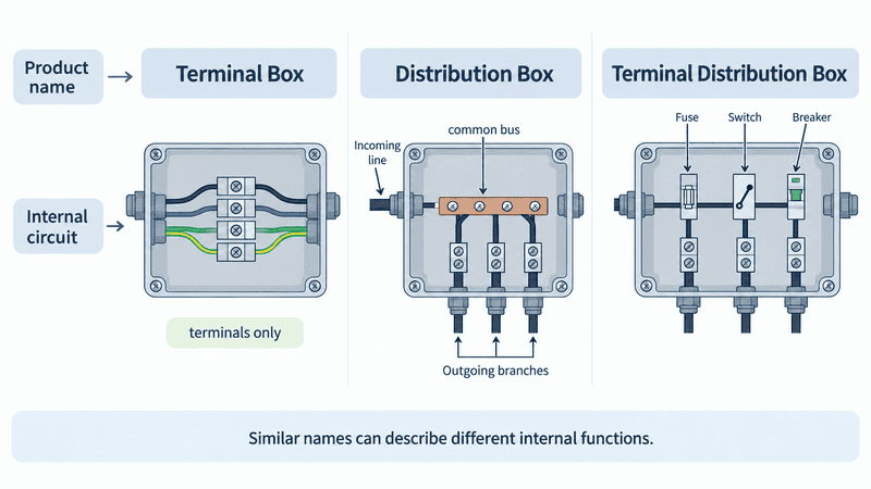
Two products can use similar names while one contains only terminal connections and the other contains a common bus, branch fuses, switches, or circuit breakers.
An enclosure manufacturer may use terminal box for a small protected housing that can accept terminals and cable glands. A terminal-block manufacturer may use distribution block for an internally commoned block with one feed and several take-off points. A control-panel supplier may use distribution box for an enclosed assembly with protective devices.
This terminology also changes by application and region. ABB describes a junction box as a central location where multiple conductors come together to create circuits and where connections are protected from physical and environmental exposure.2 That is close to some uses of terminal box, but a junction box does not automatically contain organized terminal blocks, and neither name automatically means that branch-circuit protection is installed.
Use visible features as clues, but verify the circuit:
| Product Description or Visual Clue | Likely Function | What Still Needs Confirmation |
|---|---|---|
| Empty metal or plastic enclosure with cable glands | Connection or termination enclosure | Internal terminals, DIN rail, IP rating, grounding |
| One large input terminal and several smaller outputs | One-to-many power distribution | Common bus rating, number of poles, branch protection |
| Equal input and output terminal counts | Feed-through or one-to-one routing | Whether any terminals are internally bridged |
| Replaceable fuses beside each output | Protected branch distribution | Fuse type, rating, indication, spare-fuse access |
| Rocker switch and LED for every output | Individually controlled branches | Voltage, polarity, LED function, switching rating |
| Miniature circuit breakers inside an enclosure | Distribution board or small panel | Assembly rating, incoming protection, neutral/PE arrangement |
A terminal box primarily houses organized conductor terminations; a junction box houses conductor joints or branches; a distribution block divides one electrical potential among several terminals; and a distribution box supplies multiple circuits, normally with protective devices. These terms overlap in everyday use, but their primary functions are different.
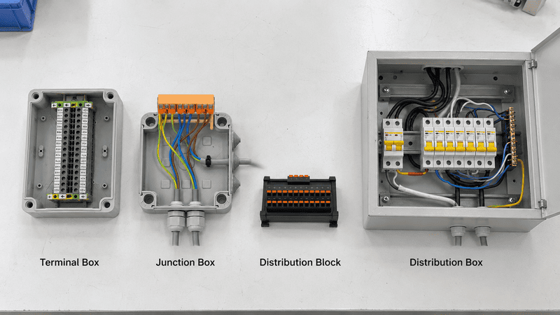
The products should be compared by enclosure, internal connection topology, and protection—not by appearance or name alone.
| Product | Primary Purpose | Enclosure | One Input to Many Outputs | Branch Protection |
|---|---|---|---|---|
| Terminal box | Terminate and organize conductors | Yes | Possible, if bridged | Not normally |
| Junction box | Join or branch conductors | Yes | Possible | Not normally |
| Feed-through terminal block | Connect one conductor to another | No, normally installed inside one | No, unless bridged | No |
| Distribution terminal block | Distribute a common potential | Usually a component housing | Yes | Not normally |
| Power distribution module | Distribute power through a compact module | Module housing | Yes | Optional |
| Distribution box or panel | Supply several outgoing circuits | Yes | Yes | Normally included |
A terminal box is an enclosure prepared for orderly conductor termination. It may contain a mounting plate, DIN rail, feed-through terminals, PE terminals, cable glands, labels, and strain-relief components.
Its defining purpose is to protect and organize connections. It may distribute power if jumpers or distribution blocks are installed, but that function must be shown in the design.
A junction box provides a protected location for conductor joints, taps, or branches. The conductors may be joined with terminal blocks, splicing connectors, or another approved connection system.
A junction box can therefore contain terminal blocks, but the word junction describes the wiring function, while terminal emphasizes the connection method.
A distribution terminal block has an internal conductive connection that distributes a feed potential to several terminal points. Phoenix Contact, for example, describes distribution blocks with integrated bridging in which each block carries one potential.3
This is different from a normal feed-through terminal, where each circuit remains independent unless a jumper is added.
A power distribution module normally combines terminals with a PCB, bus, or preconfigured bridge system. Depending on the design, it may also include:
The module may sit inside a larger cabinet and therefore should not automatically be described as a complete weatherproof box.
A distribution box or panel receives a supply and distributes it to several outgoing circuits. It commonly contains circuit breakers or fuse devices, busbars, neutral terminals, and protective-earth connections.
IEC 61439-3, for example, addresses distribution boards intended to be operated by ordinary persons and describes enclosed assemblies with outgoing circuits and protective devices.4 That product class is different from a small passive terminal-distribution component mounted inside an industrial cabinet.
A passive terminal distribution box receives one or more electrical potentials and routes them through terminals, bridges, busbars, or PCB conductors to multiple outgoing connections. It does not automatically change the voltage, amplify a signal, or provide isolation.
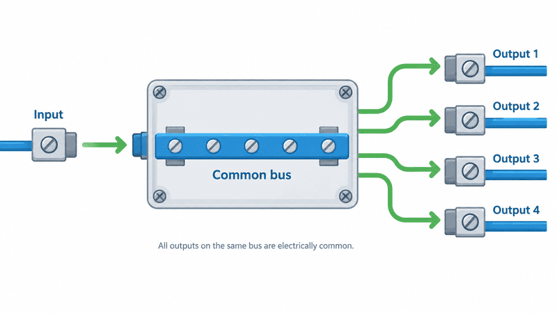
In a common-potential distribution circuit, all outputs connected to the same internal bus are electrically common. Opening one branch requires a separate fuse, switch, disconnect, or breaker in that branch.
The simplest arrangement has three parts:
For a 24 VDC system, separate distribution sections may be used for +24 V, 0 V, and protective earth. Their treatment depends on the system design; they should not be combined merely because the terminals fit in one housing.
| Internal Topology | Electrical Relationship | Typical Use |
|---|---|---|
| One input to many outputs | All outputs share one potential | Distributing +24 VDC or another common supply |
| Two independent buses | Each bus distributes a different potential | +24 V and 0 V distribution |
| One-to-one feed-through | Each input connects only to its matching output | Connector breakout or organized field wiring |
| Individually switched branches | Each output can be turned on or off | Device isolation and maintenance |
| Individually fused branches | Each output passes through its own fuse | Localized overcurrent protection |
| Relay-controlled branches | Control input operates a separate output circuit | PLC-to-load switching or isolation |
The internal topology must be confirmed by a schematic, continuity map, verified drawing, or sample test. The number of terminals alone cannot prove how the circuits are connected.
Not necessarily. A terminal or distribution block may only provide electrical connection and common-potential distribution. Branch protection exists only when the product includes correctly specified fuses, circuit breakers, electronic protection, or another protective device.
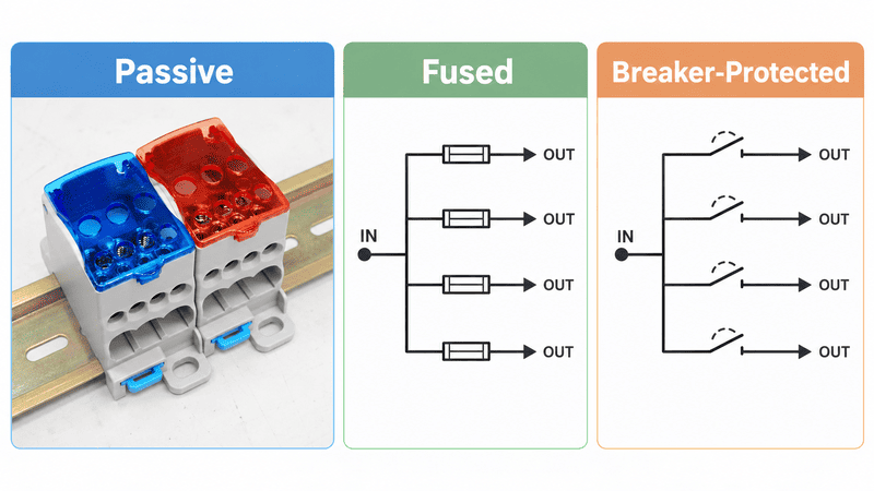
A passive common bus distributes the supply but does not isolate an overloaded branch. A fused or breaker-protected design places a protective device in the current path of each applicable output.
This is one of the most important differences to explain in an article or product page. The word distribution describes where the power goes; it does not tell us how faults are handled.
| Construction | Distributes Power | Switches a Branch | Protects a Branch | Typical Reset or Replacement |
|---|---|---|---|---|
| Passive distribution block | Yes | No | No | Not applicable |
| Disconnect terminal | Possibly | Yes, for isolation | Not by itself | Reconnect manually |
| Fuse terminal or fused module | Yes | Sometimes | Yes, when correctly selected | Replace fuse |
| Electronic protected module | Yes | Often | Yes, according to design | Reset or cycle power |
| Breaker distribution box | Yes | Yes | Yes, according to breaker specification | Reset breaker |
Manufacturer portfolios make this distinction explicit. WAGO, for example, offers potential distribution modules in both standard and fused-output versions.5 This shows why protection must be verified at product level.
A fuse or breaker also needs to be coordinated with the conductor, expected load, supply capability, and applicable equipment requirements. Simply adding a fuse holder does not establish that the complete assembly is suitable for every fault condition.
The main industrial types are enclosed terminal boxes, DIN-rail distribution blocks, potential distribution modules, fused or switched DC distribution modules, and breaker-equipped distribution boxes. The best choice depends on whether the project needs connection, distribution, branch control, protection, or a complete enclosure.
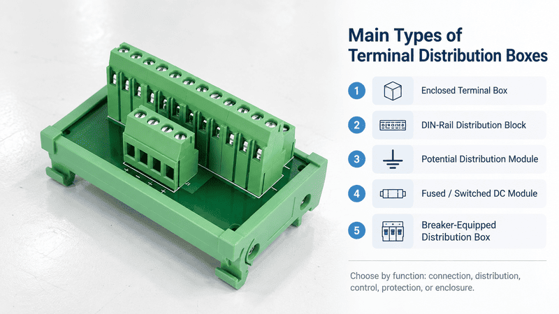
The product family should be selected from the required electrical function first, followed by current, conductor, mounting, enclosure, and documentation requirements.
This construction combines an enclosure with terminals and cable entries. It is useful when field conductors need a protected termination point outside the main cabinet.
Check the enclosure material, cable glands, sealing method, mounting plate or DIN rail, grounding provision, and actual ingress-protection rating of the complete assembled box.
This is a compact component used inside a cabinet or enclosure. One feed connection may supply several smaller output connections through an integrated bridge.
Schneider Electric describes power distribution blocks as components used to splice or distribute conductors within control panels.6 They are not automatically complete distribution boxes simply because they distribute power.
A potential distribution module provides preconfigured common-potential connections in a compact DIN-rail housing. It can reduce the number of individual terminal blocks and jumpers needed for repeated +24 V, 0 V, or another shared potential.
This type is useful when high connection density and clear labeling matter more than individual branch switching.
This module adds branch functions such as:
It is suitable when the operator needs to isolate, identify, or protect individual loads without rewiring the common supply.
This is a more complete assembly with an enclosure and protective devices for outgoing circuits. It is closer to a panelboard or consumer distribution board than to a compact terminal module.
If the project requires mains distribution, high fault-current handling, or compliance as a complete low-voltage assembly, the design and verification requirements go beyond choosing a terminal block.
| Type | Best Fit | Main Limitation |
|---|---|---|
| Enclosed terminal box | Protected field termination | Distribution and protection depend on installed components |
| Distribution terminal block | Compact one-to-many connection | Usually no branch switching or protection |
| Potential distribution module | Dense control-voltage distribution | Not a complete environmental enclosure |
| Fused/switched distribution module | Serviceable protected branches | Must match voltage, current, fuse, and polarity requirements |
| Breaker distribution box | Complete multi-circuit power distribution | Larger, more complex, and subject to assembly-level requirements |
These labels are not interchangeable. “1-in/8-out” often means one common input distributed to eight outputs, while “8-channel” may mean eight independent switched, fused, or signal circuits. “2-in/8-out” is ambiguous until the internal wiring is shown.
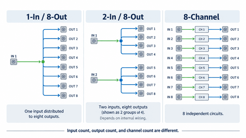
Input count, output count, terminal count, and channel count describe different things. A verified wiring diagram should define the relationship between them.
When a customer asks me about a module using only an input/output number, I use that number as the beginning of the discussion. My next question is whether the outputs are internally commoned, paired by polarity, independent, fused, switched, or mapped one-to-one.
| Label | Common Interpretation | Important Question |
|---|---|---|
| 1-in/4-out | One input feeds four common outputs | Are all four outputs directly connected? |
| 1-in/8-out | One input feeds eight common outputs | What are the total and branch current limits? |
| 2-in/8-out | Could mean two buses, two feed points, or eight output pairs | Does it distribute +V and 0 V separately, and how many outputs belong to each bus? |
| 8-channel | Eight functional branches | Are the channels passive, fused, switched, relay-controlled, or independent? |
| 10-in/10-out | Often ten one-to-one circuits | Is IN 1 connected only to OUT 1? |
| 16 points | Sixteen electrical points or PLC I/O references | How many terminals and common connections are required? |
For a more detailed explanation of one-to-one wiring, shared potentials, and channel counts, see our PLC Interface Modules Explained guide.
Select the product from the required internal circuit first. Then confirm system voltage, AC or DC, current per branch, total bus current, number of potentials, protection, conductor range, mounting, enclosure, environmental conditions, and required approvals.
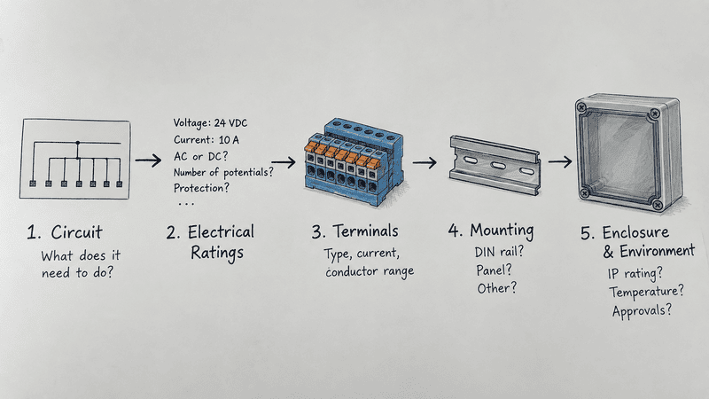
A reliable selection starts with the circuit relationship and ends with mechanical, environmental, documentation, and production requirements.
Start by choosing the job the assembly must perform:
Do not add functions merely because they sound useful. Every fuse, switch, LED, relay, or connector changes the circuit and the selection requirements.
Record the nominal voltage and the maximum voltage that may appear in normal operation. For DC products, confirm polarity. For AC products, confirm phase arrangement, frequency where relevant, neutral treatment, and protective-earth requirements.
A product marked for 24 VDC should not be treated as suitable for mains AC merely because its terminals accept the same wire.
A simple marked sketch can prevent most naming confusion. Show:
If the existing product is being replaced, a continuity test and verified circuit diagram are more useful than a front photograph alone.
Each outgoing branch has a load current, while the feed terminal and common conductive path may carry the combined current of all simultaneously operating branches.
The basic relationship is:
Required common-path current ≥ sum of all simultaneously operating branch currents
This initial sum must then be checked against startup or inrush current, ambient temperature, conductor size, installation conditions, protective-device coordination, and the manufacturer’s complete-product rating.
Confirm:
The correct protective arrangement depends on the complete circuit, not just the distribution module.
Common options include:
The selection should match conductor type, wire range, ferrule use, expected vibration, installation speed, maintenance access, and required torque or tooling.
A single-pole block may distribute one positive or phase conductor. A complete circuit often also requires a return, neutral, PE, or additional voltage group.
Distribution blocks that carry one common potential differ from device terminal arrangements that route several potentials without one integrated bridge across every point. This is why pole count and terminal count should not be treated as the same specification.
Specify whether the product needs:
Also confirm usable width, height, depth, wiring bend radius, fuse-replacement clearance, and access to switches or labels. WAGO’s rail-mounted ranges illustrate that products may be available for different DIN-rail sizes or direct mounting, depending on the family.7
If the product is installed inside a closed control cabinet, the bare module may not need its own outdoor-rated enclosure. If it is installed near the machine or outdoors, confirm:
IEC explains that IP ratings under IEC 60529 apply to the resistance of enclosures against intrusion by solids and liquids.8 Therefore, the IP claim should apply to the complete assembled enclosure—including cover, seals, cable entries, and unused openings—not merely to the terminal block installed inside it.
The relevant requirements depend on product type, end equipment, market, and installation. Terminal-block evaluation may involve standards such as UL 1059 or ANSI/UL 60947-7 series in North American projects.9 A complete low-voltage distribution assembly may be evaluated under a different set of assembly requirements.
Ask for the documents the project actually requires:
Do not assume that every component approval transfers automatically to the completed box or machine.
Check at least three different current limits: current per output branch, combined current through the common input path, and the rating of every component in that path. The lowest applicable complete-product limit controls the design.
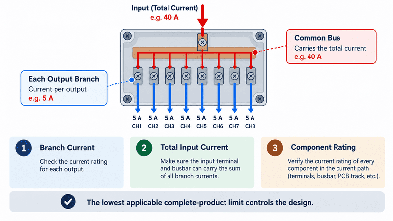
The input terminal, busbar or PCB track may carry the sum of several branch currents even when each individual output carries only a small load.
For example, assume a distribution module supplies six sensors drawing 0.10 A each and two valves drawing 0.70 A each when energized:
Total simultaneous load = (6 × 0.10 A) + (2 × 0.70 A) = 2.00 A
That 2.00 A is only the initial continuous-load calculation. The engineer must still check valve inrush, simultaneous operation, ambient temperature, conductor sizes, voltage drop, fuse coordination, and the rated current of the complete terminal/module path.
| Current Check | Why It Matters |
|---|---|
| Load current per branch | Determines branch conductor, terminal, switch, and fuse requirements |
| Total simultaneous current | Determines feed terminal, bus, connector, and PCB-path loading |
| Startup or inrush current | Can exceed the normal running current of valves, lamps, motors, and capacitive loads |
| Protective-device rating | Must protect the applicable conductor and circuit without nuisance operation |
| Ambient-temperature effect | Enclosed or densely packed products may require manufacturer derating |
| Connector and PCB rating | May be lower than the visible terminal block rating |
This is why I do not use the current printed on one terminal component as proof of the rating of the complete distribution module. The feed connector, copper path, fuse holder, switch, PCB, and output terminal must all be evaluated as one current path.
A typical 24 VDC arrangement routes the positive supply through the required main and branch protective devices to the loads, while 0 V returns through a separate common-return path. Protective earth remains a separate protective function. The exact circuit must follow the equipment design and product instructions.
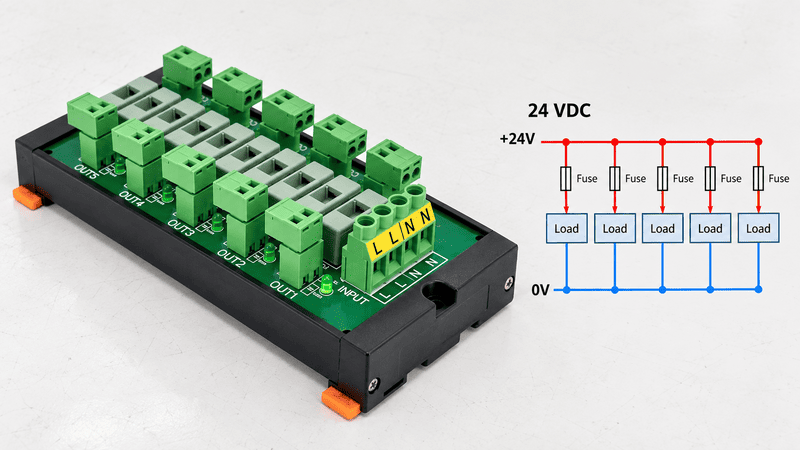
A conceptual 24 VDC system uses separate +24 V and 0 V paths. Each protected positive branch passes through its assigned fuse before supplying the load.
A common sequence is:
24 VDC power supply → upstream protective device → distribution input → branch fuse or switch → load
The return side follows a separate route from each load to the 0 V distribution terminals and back to the power supply. Whether 0 V is bonded to PE at any point is a system-level design decision and should not be improvised at the distribution module.
| Connection | Typical Role | Check Before Wiring |
|---|---|---|
| +24 V input | Feeds the positive distribution path | Polarity, total current, upstream protection |
| 0 V input | Feeds or collects the return path | Common arrangement and conductor capacity |
| Branch output | Supplies one load or downstream circuit | Branch current, fuse, switch, label |
| PE terminal | Protective conductor connection | Approved PE terminal and bonding method |
| LED circuit | Shows power or branch status | Voltage, polarity, and what condition it indicates |
| Shield terminal | Terminates cable shielding where designed | EMC concept and bonding location |
Before installation, isolate the supply, verify the absence of voltage, and follow the product instructions and applicable electrical rules. Final design and wiring should be checked by a qualified person familiar with the equipment and installation.
If the project also needs an AC-to-DC power supply, enclosure, branch protection, and terminal distribution as one system, see our guide to a complete 12V power supply box. A power supply box converts and distributes power; a passive distribution module does not perform AC-to-DC conversion.
They are used wherever several devices need organized connection or a shared supply, especially in control cabinets, automated machines, sensor systems, auxiliary DC circuits, lighting controls, and equipment retrofit projects.
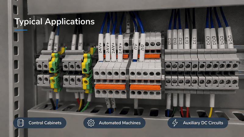
DIN-rail distribution components create an accessible connection layer between the power source and multiple field loads inside a control cabinet.
| Application | Typical Need | Suitable Product Direction |
|---|---|---|
| PLC control cabinet | Distribute 24 VDC and 0 V to sensors or interface devices | Potential distribution module |
| Automated machine | Supply valves, lamps, sensors, or auxiliary devices | Fused or switched distribution module |
| Sensor network | Repeated positive and common connections | Multi-level or sensor distribution terminals |
| LED or signaling system | One DC supply feeding several branches | Protected DC distribution module |
| CCTV or monitoring equipment | Central DC supply to several devices | Fused multi-output distribution box |
| Machine retrofit | Replace disorganized splices with labeled terminations | Enclosed terminal box or DIN-rail terminals |
| Test equipment | Isolate and identify several auxiliary circuits | Switched and indicated distribution module |
| Building electrical circuits | Distribute mains supply through protective devices | Properly rated distribution board, not a small passive module |
For industrial projects, the most valuable function is often not simply “more outputs.” It is making the wiring easier to identify, test, isolate, and maintain without confusing independent circuits with commoned terminals.
Send the electrical function, input/output relationship, voltage, current, number of potentials, protection requirements, terminal and wire information, mounting method, enclosure conditions, quantity, and any drawing or sample reference. A photograph helps identify the construction, but it cannot replace the wiring diagram.
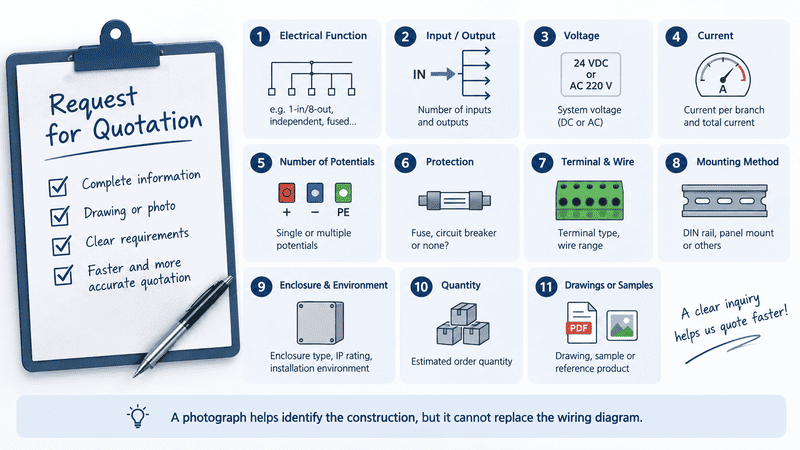
A useful inquiry combines the required internal circuit with electrical, terminal, mechanical, environmental, and production information.
When I receive this type of inquiry, I would rather ask one extra wiring question at the beginning than treat two visually similar products as electrical equivalents. The following information gives us a practical starting point:
| Information to Confirm | Example of a Useful Answer |
|---|---|
| Required function | One 24 VDC input distributed to eight fused outputs |
| Input/output topology | Common positive bus, common 0 V return, eight independent branches |
| Nominal voltage | 24 VDC |
| Current per branch | Load current for each connected device |
| Total simultaneous current | Sum of loads expected to operate together |
| Protection | Replaceable fuse per positive output |
| Switch and indication | One switch and one status LED per channel |
| Terminal type | Screw, spring, push-in, barrier, or pluggable |
| Conductor information | Wire size, solid/stranded, ferrule use |
| Mounting | 35 mm DIN rail or panel mount |
| Enclosure | Bare module inside cabinet or complete enclosed box |
| Environment | Indoor cabinet, dust, moisture, oil, temperature |
| Dimensions | Maximum width, height, depth, and service clearance |
| Documentation | Schematic, drawing, datasheet, test or approval needs |
| Commercial information | Target quantity, annual demand, sample requirement |
For replacement or OEM projects, also send:
You can review NITAI’s current Distribution & Interface Modules and send us the drawing or circuit you need to match. If the requirement is primarily for individual wiring components rather than a complete module, our terminal block range is the more relevant starting point.
The most common errors are selecting from the name or appearance alone, assuming every output is independent, assuming protection is included, checking only branch current, and applying an enclosure rating to a bare internal module.
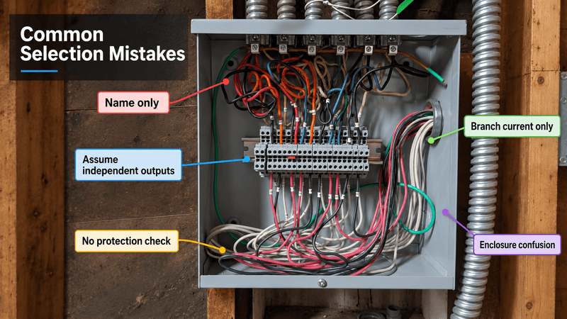
A short schematic and a complete current check prevent more errors than a long but vague product name.
| Mistake | Why It Causes Problems | Better Check |
|---|---|---|
| Selecting from “terminal distribution box” alone | The phrase covers several product classes | Define the internal function and enclosure |
| Counting terminals as channels | Common and PE terminals may increase terminal count | Verify the circuit for every channel |
| Assuming all outputs are independent | Several outputs may share one internal bus | Check bridges, PCB tracks, and continuity |
| Assuming every branch is protected | Passive distribution provides no branch interruption | Locate the fuse, breaker, or electronic protection |
| Checking only current per output | Feed and common path may carry all branch currents | Calculate total simultaneous current |
| Using terminal rating as module rating | PCB, connector, switch, or bus may be the limiting part | Use the complete-product rating |
| Treating 0 V, neutral, PE, and shield as interchangeable | They have different electrical and safety functions | Follow the system grounding and EMC design |
| Assuming an enclosure IP rating covers cable entries | Unsealed glands or openings can change the complete rating | Verify the assembled box and every entry |
| Copying a sample from appearance alone | Internal mapping may differ | Obtain a schematic or perform controlled continuity verification |
| Claiming component approval for the complete box | Assembly construction affects compliance | Confirm the exact product and assembly documentation |
Not always. A junction box primarily houses wire joints or branches. A terminal distribution box normally contains organized terminal connections and may distribute a common supply to multiple outputs. Some suppliers use the terms loosely, so the internal components and wiring must be checked.
No. A terminal box mainly provides a protected location for terminations. A distribution box receives a supply and feeds several outgoing circuits, normally with protective devices. A terminal box can contain distribution components, but this is a design feature rather than an automatic property of the name.
No, not unless it contains a power supply, converter, transformer, or another voltage-conversion component. A passive terminal distribution box normally passes the supplied voltage to its connected outputs.
Outputs connected to the same passive bus normally share the same electrical potential, subject to voltage drop under load. Products with several independent buses, relays, converters, or switched circuits may behave differently. Check the schematic.
No. Many distribution terminal blocks are passive. Fuses are present only in products specifically designed as fused terminal blocks or fused distribution modules.
A distribution block normally provides direct conductive distribution through terminals and bridges. A distribution module may use a PCB or bus structure and may add fuses, switches, LEDs, relays, connectors, or other functions. Naming still varies by manufacturer.
Only if the exact product is rated and designed for the required system. Voltage type and level affect insulation, polarity-sensitive components, switching, protection, spacing, and documentation. Never infer AC suitability from a DC product—or the reverse—without verified ratings.
It commonly means one input is internally connected to eight output terminals. However, it does not state the total current rating, branch protection, polarity arrangement, or whether a separate return bus is included. The wiring diagram remains necessary.
No. A passive module does not provide the branch protection, fault interruption, enclosure, and assembly functions expected from a properly designed breaker distribution panel.
No. DIN-rail mounting is common in control cabinets, but terminal and distribution products may also be mounted directly to a panel, flange, PCB, or enclosure. Confirm the exact mounting method and required clearance.
That depends on where it is installed. A bare module inside an already protected cabinet may rely on the cabinet enclosure. A standalone box exposed to dust or water requires a suitable complete-enclosure rating, including its seals and cable entries.
A photograph helps identify the housing, terminals, fuses, switches, and mounting style, but it cannot prove the internal mapping or current capacity. Use the model number, schematic, verified continuity map, dimensional drawing, and sample testing where necessary.
A terminal distribution box is not one universal product. The phrase may describe an enclosed terminal assembly, a junction or connecting box, a one-to-many distribution block, a fused or switched power distribution module, or a complete breaker-equipped distribution box.
The safest selection method is to ignore the product name for a moment and define the circuit:
In my work with terminal and interface-module inquiries, these questions provide a much clearer basis than terms such as “8-way box” or “2-in/8-out module” by themselves. Once the internal topology is clear, we can evaluate terminals, wire range, current path, mounting, enclosure, documentation, and production requirements in the correct order.
NITAI manufactures terminal blocks and supports industrial distribution and interface module projects for control-cabinet wiring. If you need help evaluating a terminal distribution product, send us the application, input/output relationship, voltage, load current, wiring diagram, dimensions, photographs, and target quantity. We can review what is confirmed, identify what still needs clarification, and help define the specification before sampling or production.
International Electrotechnical Commission, [IEC 60947-7-1:2025 — Terminal blocks for copper conductors](https://webstore.iec.ch/en/publication/72949). Official standard scope for industrial terminal blocks with screw-type or screwless clamping units. Evidence role: supports the distinction between conductor-connection terminal blocks and complete distribution assemblies. Scope note: citing the standard does not claim that every product discussed is certified to it. ↩
ABB, [Junction Boxes — Enclosures](https://new.abb.com/low-voltage/products/enclosures/junction-boxes). Official manufacturer overview describing junction boxes as protected locations where multiple conductors come together to form circuits. Evidence role: supports the junction-box function discussed in the terminology comparison. ↩
Phoenix Contact, [Distribution Blocks and Device Terminal Blocks](https://www.phoenixcontact.com/en-in/products/distribution-blocks). Official technical overview explaining integrated bridging, single-potential distribution blocks, multi-potential device terminal blocks, and function versions with disconnect or fuse elements. Evidence role: supports the distinction between passive distribution and additional branch functions. ↩
International Electrotechnical Commission, [IEC 61439-3:2024 — Distribution boards intended to be operated by ordinary persons](https://webstore.iec.ch/en/publication/68496). Official standard scope describing enclosed distribution-board assemblies with outgoing circuits and protective devices. Evidence role: supports the distinction between a distribution board and a small passive terminal-distribution component. ↩
WAGO, [Potential Distribution Modules](https://www.wago.com/sg/products/interface-electronic/potential-distribution-modules). Official product overview describing compact potential distribution and a fused-output version. Evidence role: supports the statement that protection is product-specific rather than inherent in every distribution module. ↩
Schneider Electric, [9080 Power Distribution Blocks](https://www.se.com/ca/en/product-range/7717-9080-power-distribution-blocks/). Official product-family overview describing power distribution blocks used to splice or distribute conductors within control panels. Evidence role: supports the industrial control-panel use of distribution blocks. ↩
WAGO, [Rail-Mount Terminal Blocks](https://www.wago.com/global/products/electrical-interconnections/discover-rail-mount-terminal-blocks). Official terminal-block overview covering DIN-rail and application-specific mounting options. Evidence role: supports the need to confirm rail size, mounting method, conductor technology, and available installation space. ↩
International Electrotechnical Commission, [Ingress Protection (IP) Ratings](https://www.iec.ch/ip-ratings). Official explanation of IEC 60529 and enclosure resistance to intrusion by solids and liquids. Evidence role: supports applying an IP claim to the complete enclosure configuration rather than assuming it from an internal component. ↩
UL Solutions, [Connector Certification Services](https://www.ul.com/services/connector-certification-services). Official overview listing UL 1059 and ANSI/UL 60947-7 series among standards used to evaluate terminal blocks. Evidence role: supports checking the applicable market and product-level certification rather than making a general approval claim. ↩
An M12 male connector 5-pin B-coded may look like a straightforward line item, but its name does not…
5V relay modules are used to let a low-voltage controller switch a separate electrical circuit, but many buyers…
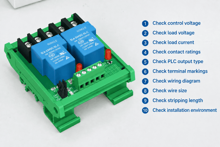
A relay module looks simple until a control cabinet fault appears after commissioning. One wrong assumption about COM,…
NITAI manufactures terminal blocks, M8/M12 waterproof connectors and industrial distribution modules for global OEMs, distributors and automation customers.
Leave a Reply