Oct 17, 2026
How Do I Choose the Right M8 8 Pin Female Connector for My Equipment?
An M8 8 pin female connector can look like the right replacement on a purchasing list and still…

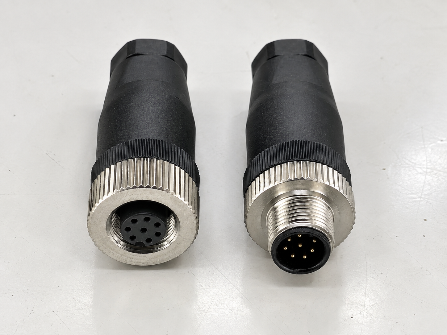
An M12 8-pin connector is used when one compact industrial connection must carry more circuits than a typical 3-, 4-, or 5-pin sensor connector, or when an X-coded interface must carry four Ethernet data pairs. A-coded 8-pin versions are commonly selected for device-specific multi-signal connections such as encoders, feedback devices, safety equipment, or camera power and I/O. X-coded 8-pin versions are designed for four-pair Industrial Ethernet. Eight pins are not automatically better: the correct choice depends on the equipment pin assignment, coding, electrical load, data rate, cable, shielding, and installation environment.
An M12 8-pin interface can serve either a device-specific multi-signal connection or a four-pair industrial data connection. The coding and equipment documentation determine which one it is.
When customers ask us for an “M12 8-pin cable,” the pin count is only the beginning of the selection process. We first ask what equipment the cable connects, what each circuit must carry, and whether the port is A-coded or X-coded. Two connectors can both have eight contacts and still be mechanically incompatible, electrically incompatible, or intended for completely different applications.
This article focuses on where M12 8-pin connectors are actually used, why a device may need eight contacts, and when a lower pin count is the better choice. It does not repeat a complete pinout, conductor-color table, male/female identification guide, or wiring-view tutorial; those details should always be checked against the connector drawing and the connected equipment manual.
Some devices need eight pins because they must route several independent power, feedback, control, safety, or data circuits through one compact sealed interface. The extra contacts are useful only when the equipment architecture actually requires them.
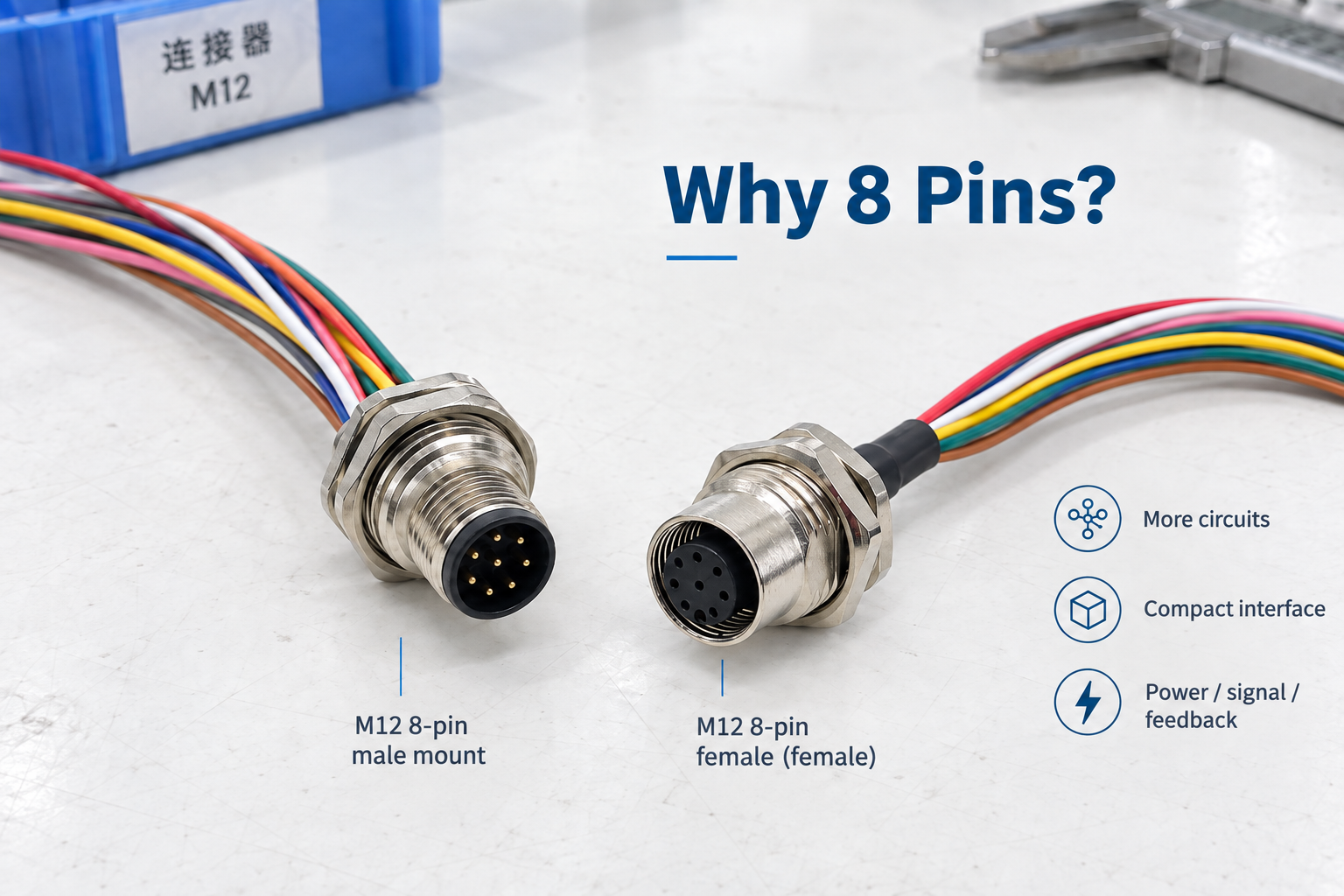
Eight contacts can consolidate several low-voltage circuits into one interface, or form four controlled pairs for Ethernet. These are two different design purposes and should not be confused.
A basic proximity sensor may need only positive supply, 0 V, and one switching output. A more complex device may need power plus several outputs, differential feedback channels, a reference circuit, a trigger input, or additional status lines. Using one 8-pin connector can reduce the number of separate cable entries and simplify equipment replacement.
The following examples explain the reason for the contact count, not a universal pin assignment:
| Device requirement | Why more contacts may be needed | Possible circuit combination | What must be confirmed |
|---|---|---|---|
| Position or speed feedback | Several feedback channels must return to a controller | Supply, 0 V, A/A̅, B/B̅, and optional reference signals | Encoder manual, output type, voltage, shielding, and exact pin map |
| Multi-channel sensing | One housing provides several independent outputs | Supply, common, multiple digital or analog outputs, and status | Whether outputs share a common, signal type, and input compatibility |
| Machine-vision auxiliary I/O | A camera or illuminator needs functions beyond network data | Power, trigger, strobe, digital I/O, and reference conductors | Whether the port is for data, power/I/O, or both |
| Safety equipment | Several safety and diagnostic circuits must be connected | Dual safety channels, lock control, auxiliary status, and supply | Approved safety-device wiring and required performance level |
| Compact controller or custom machine unit | The manufacturer combines several circuits in one port | Application-specific power, inputs, outputs, or communication | The original drawing and device model; never infer from color alone |
| Four-pair Ethernet | The network requires four controlled data pairs | Four balanced pairs in an X-coded interface | Network standard, cable category, shielding, length, and equipment ports |
IEC 61076-2-101 covers M12 screw-locking connectors from 2 to 17 positions for signal, data, and power applications.1 That range makes the M12 family flexible, but it also means that “M12” and “8-pin” do not define the electrical function by themselves.
In our work, the safest rule is simple: choose the contact count from the equipment circuit requirement, not from the idea that more pins must provide better performance.
A-coded M12 8-pin connectors are used mainly for device-specific multi-signal connections where eight separate conductors are needed. Typical examples include certain encoders, position-feedback devices, multi-output sensors, safety switches, camera power/I/O ports, compact controllers, and custom machine interfaces.
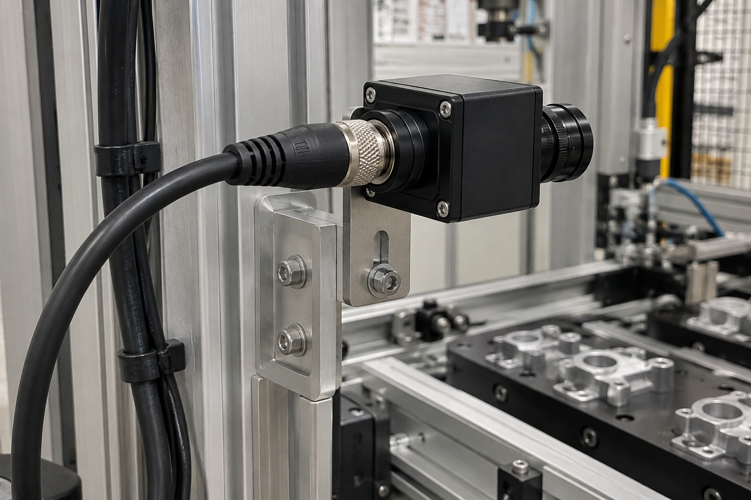
A-coded 8-pin ports often combine several low-voltage functions in one connector. Their electrical assignments remain device-specific even when the mechanical interface is standardized.
An A-coded 8-pin connector does not have one universal signal definition. The equipment manufacturer may assign the contacts to power, digital outputs, analog signals, differential feedback, safety channels, trigger circuits, or other functions. A cable that works on one 8-pin device can therefore damage or fail on another device even if it mates mechanically.
| Equipment type | Why an 8-pin interface may be used | Selection question we ask first |
|---|---|---|
| Incremental encoder or position-feedback device | Differential channels and reference signals can require more conductors than a basic sensor | What is the exact output circuit: HTL, TTL/RS-422, open collector, or another design? |
| Multi-output sensor | Several measurement or switching outputs leave one device | Which outputs are digital, analog, complementary, or diagnostic? |
| Safety interlock or guard-locking device | Safety channels, lock control, auxiliary status, and supply may share one port | Which approved wiring diagram belongs to the exact model and safety architecture? |
| Machine-vision auxiliary port | Power, trigger, strobe, and discrete I/O can be combined | Is the connector an auxiliary I/O port rather than the Ethernet port? |
| Compact remote unit or machine module | Multiple inputs and outputs pass through one sealed connection | Is the interface proprietary or tied to a specific controller? |
| Custom OEM equipment | The equipment designer defines a dedicated eight-circuit interface | Can the customer provide the drawing, mating part number, and functional assignment? |
Official product ranges also show how device-specific these uses can be. For example, KEYENCE offers an M12 8-pin-to-5-pin conversion accessory for particular safety interlock models rather than describing it as a universal adapter.2 The lesson is not that every safety switch uses eight pins; it is that the connector must be matched to the exact equipment series and approved circuit.
An incremental encoder may need two supply conductors plus paired A and B channels and an index/reference channel. That can make an 8-conductor connection practical. However, another encoder may use fewer signals, a serial interface, or a completely different contact assignment.
We therefore never build an encoder cable from the words “M12 8-pin” alone. We ask for:
That process takes longer than choosing by a product photo, but it prevents the most expensive mistake: a cable that fits and is wired incorrectly.
No. The IO-Link Interface and System Specification states that Class A ports use M5, M8, or M12 connectors with a maximum of five pins, while Class B ports use 5-pin M12 connectors; the M12 interfaces are mechanically A-coded.3 An 8-pin A-coded cable may exist elsewhere on a machine that also uses IO-Link, but that does not make the 8-pin connection a standard IO-Link port.
X-coded M12 8-pin connectors are used for rugged four-pair Industrial Ethernet links, especially where industrial cameras, vision systems, data-acquisition equipment, industrial computers, controllers, or network switches need more bandwidth than a two-pair connection can provide.
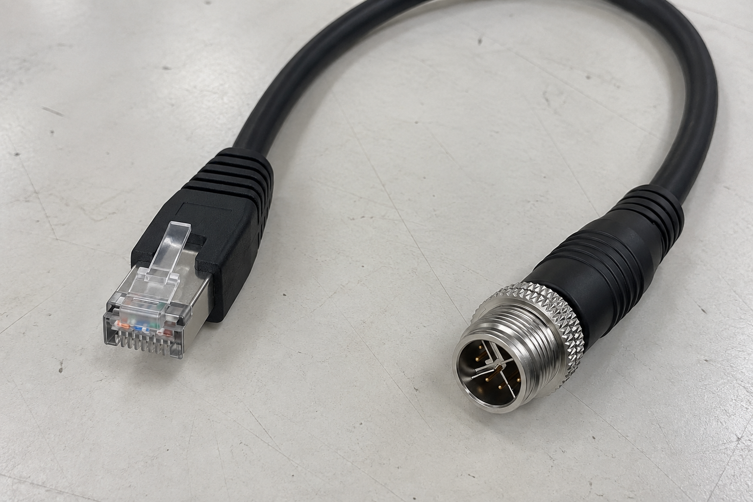
The X-shaped internal separation groups eight contacts into four pair zones. Reliable network performance depends on the complete channel, not only on the connector face.
IEC 61076-2-109 describes M12×1 connectors for data transmission up to 500 MHz and specifically identifies vision systems and data acquisition among the possible applications.4 ODVA material describes the M12-8 X-coded interface as a four-pair design associated with Category 6A performance and transmission rates up to 10GBASE-T.5
These sources explain why X-coded 8-pin connections appear in high-data applications:
| Equipment or link | Why X-coded 8-pin may be selected | What determines actual performance |
|---|---|---|
| Industrial camera | High-resolution image data must move reliably in a harsh machine environment | Camera port, required data rate, cable category, shielding, and host interface |
| Vision inspection system | Several images or high frame rates can create a larger data load | Complete channel design and the capability of both devices |
| Industrial PC or controller | Four-pair Ethernet provides a rugged machine-side network connection | Supported Ethernet standard, cable length, and connector termination |
| Industrial switch | Sealed field ports distribute Ethernet close to the machine | Port coding, network topology, installation environment, and switch specification |
| Data-acquisition equipment | High sampling or multiple channels can require a higher-throughput link | Protocol, bandwidth, EMI conditions, and channel certification |
| Robot or moving machine link | Rugged locking and an industrial cable are required | Flex rating, bend radius, torsion requirement, shielding, and service life |
No. The X-coded interface makes a four-pair industrial channel possible, but the connector head alone does not create a 10 Gigabit link. The complete assembly must preserve the required electrical performance from one device to the other.
The channel includes:
IEC 61918 treats industrial communication cabling as an installed network system and includes M12-8 X-coding in its industrial communication-network installation coverage.6 This is why we ask for the target data rate and application—not just “X-coded, 8-pin.”
For a dedicated explanation of the data interface, see What Is an M12 X-Coded Connector and When Should You Use It?.
Use eight pins only when the device requires eight independent conductors or an X-coded four-pair data channel. For a standard sensor, actuator, or IO-Link port, a 3-, 4-, or 5-pin connection is often simpler, smaller at the cable level, easier to terminate, and less likely to be wired incorrectly.
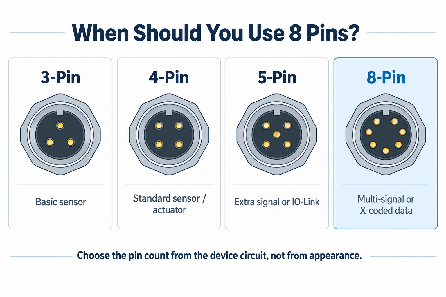
The correct pin count follows the device circuit and protocol. Unused contacts add cost and complexity without improving the connected equipment.
| Pin count | Typical reason to use it | Common application pattern | When not to move up to 8 pins |
|---|---|---|---|
| 3 pins | Supply plus one signal/output | Basic proximity sensor, photoelectric sensor, or simple actuator | When the device manual shows only three required circuits |
| 4 pins | Supply plus communication or additional I/O | Standard sensor wiring, many IO-Link Class A connections, or another defined four-contact interface | When four contacts already support the device and protocol |
| 5 pins | One additional signal or auxiliary power pair | Multi-function sensor, certain analog devices, or IO-Link Class B | When the fifth contact completes the approved interface |
| 8 pins, A-coded | Multiple device-specific circuits | Encoder, safety device, multi-channel equipment, or auxiliary camera I/O | When a simpler standardized port already carries all required functions |
| 8 pins, X-coded | Four-pair Industrial Ethernet | Vision, industrial computing, data acquisition, or higher-bandwidth machine networks | When the equipment uses another Ethernet interface or does not need a four-pair link |
If a 4-pin cable fully supports the device, replacing it with an 8-pin assembly usually adds no functional advantage. It may instead introduce a thicker cable, more termination work, and more opportunities for pin-assignment errors.
The main limits are product-specific electrical ratings, denser contacts, cable bulk, termination difficulty, non-universal pin assignments, electromagnetic compatibility, and sealing that depends on the complete mated assembly. Eight contacts fit inside the same general M12 interface, so every rating must be checked on the exact product drawing.
A successful M12 8-pin connection depends on contact ratings, cable construction, termination quality, routing, sealing, and the equipment interface at both ends.
| Limitation or risk | Why it matters | How we control it |
|---|---|---|
| Current and voltage are product-specific | The M12 family standard covers many contact arrangements; one headline rating cannot be applied to every 8-pin product | Confirm the manufacturer drawing, conductor size, ambient temperature, and simultaneous current load |
| Smaller conductors may be necessary | Eight cores or four pairs must fit inside a practical cable diameter | Calculate voltage drop and check flex, diameter, and connector cable-entry range |
| No universal A-coded pin function | Mechanical fit does not guarantee electrical compatibility | Use the device manual and an approved point-to-point wiring drawing |
| Pair geometry matters for X-coded Ethernet | Continuity can pass while return loss or crosstalk performance fails | Use the required category cable and a controlled termination process |
| Cable can be thicker or stiffer | More conductors, pair separators, and shielding affect routing | Confirm minimum bend radius, drag-chain or torsion duty, and available space |
| Field termination is less forgiving | Eight contacts increase the chance of crossed, loose, or over-stripped conductors | Use clear contact markings, suitable tools, and continuity/insulation testing |
| Coding can be misidentified | A-coded and X-coded 8-pin products serve different functions | Verify the mating face, keyway, part number, and device documentation |
| Shielding can be incomplete | A shielded cable without effective connector bonding may not control interference | Define shield coverage, 360-degree termination, and grounding at system level |
| IP performance depends on assembly condition | A connector may meet its declared protection only when correctly mated and tightened | Check the exact product IP rating, seal, torque, cap, and cable gland |
The IP code comes from IEC 60529 and describes protection against access, solid foreign objects, and water under specified test conditions.7 It does not mean that every M12 8-pin connector is automatically waterproof in every installation. An IP-rated product must still be correctly assembled, mated to a compatible part, and used within its documented conditions.
IEC 61076-2-101 defines a family that includes many numbers of contacts and intended functions.1 A rating listed in the scope of the family or on another M12 model is not automatically the rating of the 8-pin product in your hand. Contact geometry, wire gauge, temperature, materials, and derating can all change the allowable load.
For quotations and drawings, we therefore avoid statements such as “all M12 8-pin connectors are 4 A” or “all X-coded cables are 10G.” We confirm the exact design and state only the rating that the selected product and cable assembly can support.
The best construction depends on whether the connection is a finished machine cable, a field repair point, an enclosure port, a PCB interface, or an Ethernet transition. Coding and pin count come first; body style, termination, cable, and mounting come next.
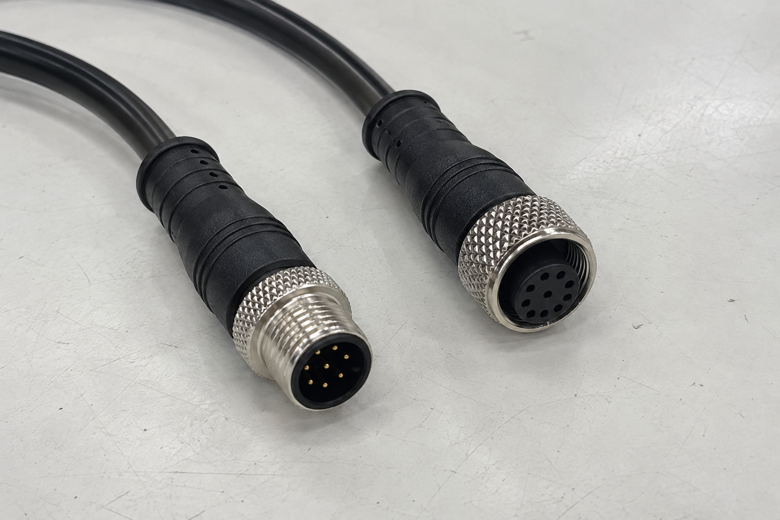
The same front interface can be supplied as an overmolded cordset, field-wireable connector, panel receptacle, PCB connector, or M12-to-RJ45 assembly. The rear construction must match the installation.
| Product construction | Best suited to | Main information to confirm |
|---|---|---|
| Overmolded cable assembly | Repeat production, factory-tested machines, and harsh environments | Coding, gender, wiring, cable length, jacket, shielding, and opposite end |
| Field-wireable connector | On-site installation, repair, or adjustable cable length | Conductor size, cable diameter, termination method, shield connection, and installer skill |
| Front-mount receptacle | Equipment wall or panel installed from the outside | Panel cutout, panel thickness, sealing, rear termination, and mounting thread |
| Rear-mount receptacle | Internal installation with a clean external interface | Accessible mounting direction, body length, panel thickness, and seal position |
| PCB or solder receptacle | Direct connection to the device electronics | PCB footprint, contact orientation, solder process, mounting height, and mechanical support |
| Straight connector | Open installations with enough axial clearance | Bending space behind the connector and cable strain relief |
| Right-angle connector | Shallow cabinets or ports close to a machine surface | Cable-exit direction after the keyway is aligned and coupling is tightened |
| X-coded M12-to-RJ45 cable | Transition from a sealed machine port to a conventional Ethernet port | Pair map, category, shield continuity, RJ45 type, data rate, and environment at both ends |
Field-wireable 8-pin products are available from established manufacturers, but their conductor range, cable-entry diameter, termination method, and environmental rating vary by model.8 For stable repeat production, an overmolded cable assembly usually reduces assembly variation. For commissioning or repair, a field-wireable design may be more practical.
Cable jacket selection also depends on the environment. PVC may be suitable for fixed general industrial use, while PUR is often chosen where abrasion, oil exposure, or repeated movement is more demanding. The jacket name alone does not define the connector's IP rating. See our comparison of PUR and PVC cable for the separate material decision.
At NITAI, we confirm the equipment, function, coding, mating side, circuit assignment, construction, cable, and environment before we confirm an M12 8-pin solution. A clear drawing and sample test are more reliable than selecting from a photo or product title.
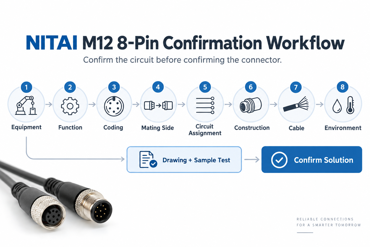
Our confirmation process moves from the device and circuit requirement to the connector, cable, drawing, and sample. This order prevents a mechanically correct but electrically wrong selection.
When a customer sends us a connector photo, we use the photo to begin identification—not to approve production. A side view can show the body shape, but it may hide the coding, contact gender, pin numbers, and equipment label. We ask for a front mating-face photo and the device information before deciding what the customer needs.
| Customer evidence | What we verify | Problem it helps prevent |
|---|---|---|
| Equipment brand and full model | Original manual, port function, and electrical requirements | Using a generic cable on a proprietary interface |
| Clear mating-face photo | Contact count, coding, gender, and keyway | Ordering an A-coded part for an X-coded port or the wrong mating side |
| Manufacturer pin assignment | Function of every contact at both ends | Crossed power, signal, safety, or data circuits |
| Existing cable label or part number | Cable type, approvals, and original construction | Replacing a controlled product with an unsuitable generic assembly |
| Opposite-end connector photo or drawing | Complete point-to-point connection | Correct M12 end but incorrect controller or cabinet end |
| Voltage and current | Contact and conductor suitability | Excessive temperature rise or voltage drop |
| Protocol and target data rate | A-coded signal connection versus X-coded data channel | Choosing by pin count instead of communication requirement |
| Installation description | Fixed, flexing, drag-chain, torsion, indoor, outdoor, oil, or washdown duty | Premature cable or seal failure |
| Approved drawing | Final orientation, wiring, dimensions, and materials | Different assumptions between purchasing, engineering, and production |
Our normal project sequence is:
This is the first-person experience we can responsibly share: many connector errors do not come from poor materials. They come from approving the wrong interface or pin assignment too early.
Send the device model, port function, coding, gender, pin assignment, opposite end, cable requirements, electrical or network requirements, environment, quantity, and any existing drawing. This gives us enough information to identify whether an 8-pin product is actually necessary and how it should be built.
| Information required | Useful example | Why we need it |
|---|---|---|
| Equipment manufacturer and model | Camera, encoder, safety switch, controller, or switch model | Links the cable to the correct device documentation |
| Port purpose | Feedback, safety I/O, auxiliary camera I/O, or Ethernet | Separates device-specific A-coded wiring from X-coded networking |
| Coding | A-coded or X-coded | Confirms mechanical and functional family |
| Contact gender | Male pins or female sockets | Confirms mating side |
| Required product | Same part as the photo or the mating counterpart | Prevents a common purchasing misunderstanding |
| Pin assignment | Contact-to-function table for both ends | Defines the electrical assembly |
| Voltage and load current | Supply voltage and current per circuit | Supports contact, conductor, and voltage-drop checks |
| Network requirement | Protocol and 100 Mbit/s, 1 Gbit/s, or 10 Gbit/s target | Determines X-coded cable and channel requirements |
| Cable length | For example, 2 m, 5 m, or custom | Affects voltage drop, signal integrity, and installation |
| Cable duty | Fixed, flexing, drag-chain, robotic torsion, outdoor, or oil-resistant | Determines conductor and jacket construction |
| Shielding | Unshielded, overall shield, pair shielding, or defined bonding | Supports EMC or network performance |
| Mounting | Cordset, field-wireable, front mount, rear mount, PCB, straight, or angled | Defines mechanical construction |
| Protection and approvals | Required IP rating, temperature, UL, CE-related documentation, or other project needs | Prevents assumptions about compliance |
| Quantity and validation plan | Sample quantity and expected production volume | Allows appropriate tooling, testing, and approval planning |
If the pin assignment is unknown, send the manual or original cable part number rather than guessing from conductor colors. We can discuss the interface from evidence; we should not invent a wiring map for equipment we have not identified.
An M12 8-pin connector is the wrong choice when the device uses fewer circuits, follows a different standardized interface, needs more power than the selected contacts can carry, uses another network connector, or cannot be supported by a verified pin assignment.
| Situation | Better direction | Reason |
|---|---|---|
| Basic sensor needs supply and one output | Use the specified 3- or 4-pin sensor connection | Fewer conductors make wiring and troubleshooting simpler |
| Standard IO-Link Class A or Class B port | Use the defined 4- or 5-pin A-coded connection | Standard IO-Link ports do not require an 8-pin interface3 |
| Device requires a different M12 coding | Use the coding specified by the device | Matching the M12 thread and pin count is not enough |
| Load exceeds the exact 8-pin product rating | Select a suitable power connector or separate power path | More contacts do not automatically provide more current capacity |
| Network uses another approved interface | Follow the equipment and network design | An X-coded conversion is useful only when both ends and channel are defined |
| Pin assignment cannot be verified | Stop and obtain the manual, drawing, or original part number | A cable that mates but connects the wrong circuits is not an acceptable substitute |
| Cable must fit an extremely tight moving path | Compare a lower-contact solution, distributed I/O, or another cable architecture | An eight-core or four-pair cable may be too large or stiff |
| Future expansion is the only reason | Reserve contacts only if the equipment design formally defines them | Unused pins add complexity and can create undocumented wiring later |
The best connector is not the one with the most contacts. It is the one that carries the required circuits, mates correctly, survives the installation, and can be tested against a clear specification.
The answers below address the most common application mistakes: assuming every 8-pin connector is Ethernet, treating it as a universal upgrade, or ordering without the equipment pin assignment.
No. X-coded 8-pin connectors are intended for four-pair industrial data links, while A-coded 8-pin connectors are often used for device-specific multi-signal connections. Identify the coding and port function before selecting the cable.
Only if the equipment manufacturer specifies a compatible 8-pin interface and provides the wiring. The same M12 thread does not make different contact arrangements or codings interchangeable. If the device needs four or five contacts, an 8-pin cable normally provides no benefit.
No. They have different mechanical coding and different intended functions. An A-coded 8-pin multi-signal connector is not a substitute for an X-coded four-pair Ethernet connector.
It can be, but only when the encoder specifies that interface. Eight conductors can accommodate supply and multiple feedback channels, including differential signals, but the pin assignment and output type must come from the exact encoder manual.
Some safety devices use an 8-pin interface, but the safety circuit must follow the approved device documentation. Never transfer a generic 8-pin wiring pattern to a safety function.
No. An appropriately designed X-coded Category 6A channel can support 10GBASE-T, but the cable, connectors, termination, length, shielding, installation, and connected equipment must all meet the requirement.5
An A-coded device-specific interface can carry low-voltage power and signals when the product and equipment are designed for it. Do not assume the current, voltage, or pin functions. For higher-power or standardized hybrid requirements, another M12 coding or a separate power connection may be more appropriate.
Only a complete, correctly assembled, and properly mated product can achieve its declared IP rating. The cable jacket, connector body, sealing parts, mating connector, tightening, unused-port cap, and environmental conditions all matter.7
Mechanical mating confirms only part of compatibility. The coding, contact assignment, voltage, signal type, shielding, pair structure, and viewing orientation may still be wrong. A continuity test can also miss data-channel performance problems.
No. Standard IO-Link Class A connections use up to five pins, and Class B uses a 5-pin M12 interface.3 An 8-pin connector elsewhere on an IO-Link machine is not automatically an IO-Link port.
An M12 8-pin connector is the right choice when a verified device interface needs eight separate circuits or when an X-coded four-pair Ethernet channel is required. It is not a universal upgrade from a 3-, 4-, or 5-pin connector.
For A-coded applications, start with the equipment's circuit and pin assignment. For X-coded applications, treat the connector, cable, shielding, termination, installation, and network devices as one complete channel. In both cases, confirm the coding, mating side, electrical requirements, environment, and opposite end before ordering.
When you contact NITAI about an M12 8-pin connection, send us the device model, clear mating-face photo, pin assignment, cable length, opposite-end requirement, voltage/current or data rate, movement conditions, and required protection level. We can then help you identify the appropriate M12 connector construction and prepare a drawing for confirmation before sampling. Contact NITAI to discuss your application.
International Electrotechnical Commission, [IEC 61076-2-101:2024 — M12 screw-locking circular connectors](https://webstore.iec.ch/en/publication/77773). The standard covers M12 connector interfaces from 2 to 17 positions for data, signal, and power applications. Exact ratings depend on the selected product and implementation. ↩
KEYENCE, [GS-CC1 connector for conversion from M12 8-pin to M12 5-pin](https://www.keyence.eu/products/safety/safety-interlock-switches/gs-m/models/gs-cc1/). This model-specific accessory illustrates why an 8-pin application must be checked against the exact equipment series rather than treated as a universal interface. ↩
IO-Link Community, [IO-Link Interface and System Specification, Version 1.1.4, June 2024](https://io-link.com/fileadmin/user_upload/Downloads/Package_2024/IOL-Interface-Spec_10002_V114_Jun24.pdf), Section 5.5.1. It states that Class A ports use M5, M8, and M12 connectors with a maximum of five pins and that Class B ports use 5-pin M12 connectors. ↩
International Electrotechnical Commission, [IEC 61076-2-109:2014 — M12 connectors for data transmission up to 500 MHz](https://webstore.iec.ch/en/publication/4425). The IEC scope includes IP65/IP67 connector designs and identifies vision systems and data acquisition as application examples. ↩
ODVA, [Recent Physical Layer Updates to EtherNet/IP, 2014 ODVA Industry Conference](https://www.odva.org/wp-content/uploads/2022/06/2014_ODVA_Conference_Woodman_Recent_PL_Updates_to_Ch8_FINAL.pdf). The paper describes M12-8 X-coding as a four-pair interface associated with Category 6A performance and 10GBASE-T transmission. ↩
International Electrotechnical Commission, [IEC 61918:2018+A1:2022+A2:2024 — Installation of communication networks in industrial premises](https://webstore.iec.ch/en/publication/93274). The current consolidated edition includes coverage of M12-8 X-coding within industrial communication-network installation requirements. ↩
International Electrotechnical Commission, [IP ratings and IEC 60529](https://www.iec.ch/ip-ratings). IP codes describe tested degrees of enclosure protection; the declared rating must be applied under the conditions stated for the complete product. ↩
Baumer, [Field-wireable female M12 8-pin connector](https://www.baumer.com/in/en/product-overview/io-link-and-connectivity-technology/cables-connectors/field-wireable-connector/female-connector-m12-8-pin-straight-without-cable/p/28334). Manufacturer data for any field-wireable product should be checked for conductor range, cable entry, termination, ratings, and environmental limits. ↩
An M8 8 pin female connector can look like the right replacement on a purchasing list and still…
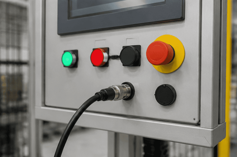
An M12 male connector 5-pin B-coded may look like a straightforward line item, but its name does not…
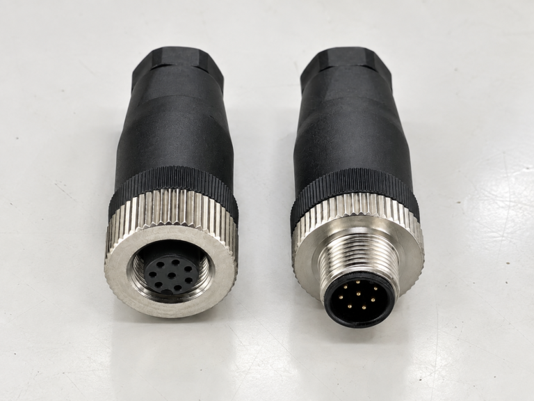
M12 connectors can carry different voltage ratings, so a buyer cannot choose one safely from the connector size…
NITAI manufactures terminal blocks, M8/M12 waterproof connectors and industrial distribution modules for global OEMs, distributors and automation customers.
Leave a Reply