Oct 16, 2026
What Is an M12 Male Connector 5-Pin B-Coded?
An M12 male connector 5-pin B-coded may look like a straightforward line item, but its name does not…

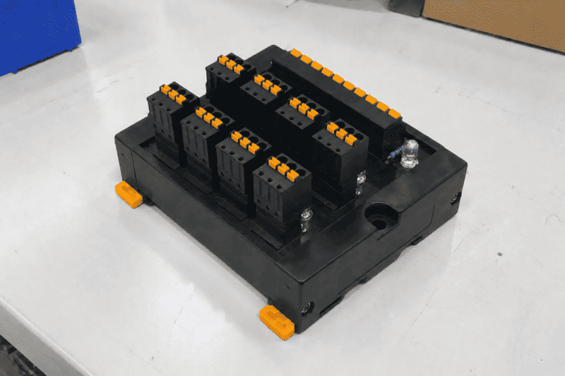
A module in PLC can sound simple, but the term often creates confusion during sourcing, cabinet wiring, and supplier communication. If a buyer asks for the wrong “module,” the RFQ may lead to mismatched parts or cabinet rework. The practical solution is to clarify the module function, signal type, wiring method, and connection interface first.
A module in PLC is a functional unit used to support, expand, or connect a PLC system.1 It may refer to an internal PLC module, such as CPU, power, I/O, or communication modules, or to an external interface, relay, or distribution module used for wiring PLC signals to field devices.
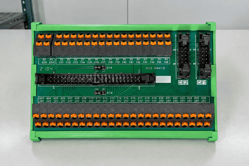
In customer RFQs, I often see one phrase used for several different products. Once the application is clear, the right module becomes much easier to identify.
A module in PLC is often understood as an internal hardware unit installed in or beside the PLC rack. This is only one meaning of the term. Buyers should separate internal PLC hardware from external wiring modules when defining a specification.
A module in PLC can perform functions such as processing logic, receiving signals, driving outputs, supplying power, or communicating with other devices. Common examples include CPU, power supply, digital input/output, analog I/O, and communication modules.2
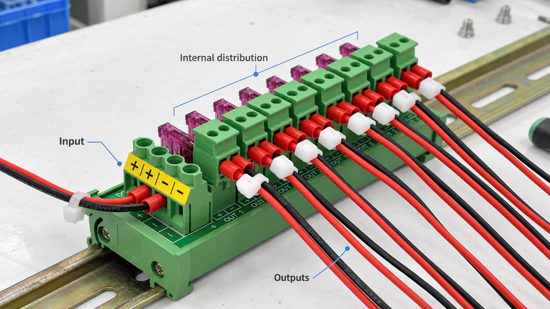
Internal PLC modules are designed for specific PLC families, backplanes, bus systems, or expansion methods.3 Buyers should verify compatibility through the PLC manufacturer's official datasheets or manuals.
Common internal PLC module types include:
From a purchasing view, buyers should check the part number, channel count, voltage, communication protocol, delivery requirements, and certification documents rather than relying only on the product name.
I have seen RFQs that simply say “PLC module, 16 channels, 24 V.” That is not enough. The module could be input or output, PNP or NPN, and may require a specific PLC series, connector, or terminal style.
A clearer internal PLC module RFQ should include:
| Internal PLC module type | Main purpose | Buyer verification point |
|---|---|---|
| CPU module | Runs PLC logic | PLC series, memory, communication ports |
| Digital input module | Reads ON/OFF signals | PNP/NPN, voltage, channel count |
| Digital output module | Drives ON/OFF loads | Output type, load current, protection |
| Analog module | Handles variable signals | Signal range, resolution, isolation |
| Communication module | Connects networks | Protocol, port type, PLC compatibility |
| Power module | Supplies PLC system | Input voltage, output capacity, approvals |
This internal meaning is important, but many customers also use “PLC module” for external interface products used between PLC I/O and field wiring.
A module in PLC usually belongs to the PLC platform, while an external PLC interface module belongs to the wiring and connection layer.
An internal PLC module expands or supports the PLC system itself. An external PLC interface module connects PLC signals to field devices, terminal blocks, cables, relays, sensors, actuators, or control cabinet wiring.5
In my work with industrial connection products, customers sometimes ask for “PLC modules” when they actually need a PLC interface module, relay module, or distribution module for cabinet wiring.
| Category | Typical product | Main function | Selected by |
|---|---|---|---|
| Internal PLC module | CPU, I/O, power, communication module | Supports PLC control system | Automation engineer, PLC designer |
| External PLC interface module | Terminal interface board, relay board, wiring module | Connects PLC wiring to terminals or relays | Cabinet builder, electrical engineer, purchaser |
| PLC distribution module | Signal distribution module, splitter module | Splits or organizes signal paths | Cabinet builder, OEM buyer, system integrator |
| Relay module | Relay interface module | Isolates or switches loads | Electrical engineer, maintenance team |
External interface modules are common in control cabinets because they simplify wiring between the PLC and field devices.6 For example, a PLC may use a high-density connector while the cabinet team needs screw terminals, spring terminals, pluggable terminal blocks, or M8/M12 connectors.
External PLC-related modules can support:
For example, a 16-channel PLC output may connect through a cable to a relay interface module, which then switches loads such as solenoid valves or indicator lamps.
If a buyer asks for a “module in PLC” but attaches a cabinet wiring photo, the supplier may quote the wrong category. Clear category language helps suppliers respond faster and purchasing teams compare quotations correctly.
Examples:
At NITAI, when module terminology is unclear, I usually ask for the wiring diagram, signal type, terminal style, channel count, and installation layout before recommending a connection product.
A module in PLC selection should not stop at the module name, channel count, and voltage. The real challenge is matching signals, loads, wiring layout, terminal style, space, and maintenance needs.
Buyers should confirm signal type, current, voltage, load type, channel count, terminal connection, cable direction, mounting method, cabinet space, labeling, service access, and required documentation.
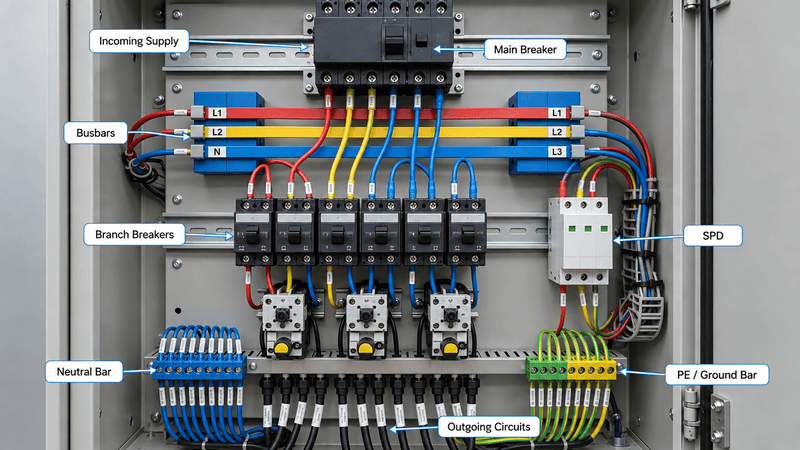
When I help customers clarify a module request, I usually begin with the signal path:
Field sensor → cable → terminal block or distribution module → PLC input PLC output → relay interface module → actuator or load
This shows where the module sits and what it connects.
Key questions include:
| Selection factor | Why it matters | Example buyer question |
|---|---|---|
| Signal type | Prevents wrong wiring and module choice | Is it DI, DO, AI, AO, power, or communication? |
| Load current | Protects contacts, relays, and traces | What is the maximum current per channel? |
| Terminal style | Affects assembly and service | Screw, spring, pluggable, or connectorized? |
| Channel count | Affects cabinet density | Do we need 8, 16, 32, or custom points? |
| Wiring direction | Affects cabinet layout | Should cables exit top, bottom, or side? |
| Mounting method | Affects installation | DIN rail, panel mount, or custom plate? |
| Documentation | Supports procurement verification | Are drawings, pinouts, and test reports available? |
The electrical function may be correct while the wiring method does not fit the cabinet. For example, the PLC side may use a multi-pin connector while the field side needs screw terminals, or the cabinet builder may need a pre-wired harness to reduce assembly labor.
Common wiring options include:
At NITAI, we support connection-oriented parts around PLC systems, including terminal blocks, interface modules, relay modules, distribution modules, waterproof circular connectors, and industrial wiring harnesses. These products are intended as wiring solutions around the selected PLC system, not replacements for PLC brand engineering.
A module that looks inexpensive on the quotation may cost more during assembly. Cabinet wiring labor is a real cost, especially across repeated machines.
Good cabinet-focused selection should consider:
For electrical safety, load protection, and compliance decisions, buyers should consult qualified engineers and verify supplier datasheets.7
A module in PLC wiring system may need a relay interface when the PLC output cannot directly handle the load, when electrical isolation is useful8, or when the cabinet requires easier maintenance.
A relay interface module sits between PLC outputs and field loads. It can allow low-power PLC signals to control higher-load circuits and separate control from load wiring. Buyers should confirm coil voltage, contact rating, channel count, relay type, and terminal layout through datasheets.
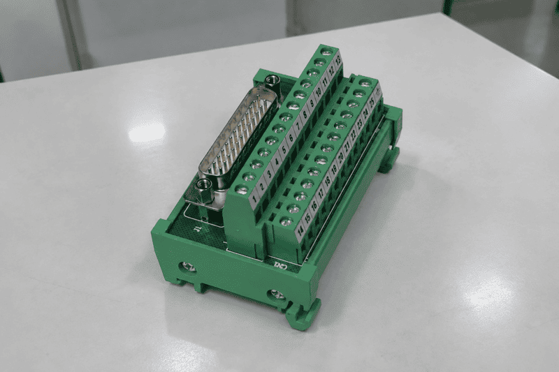
A relay module is not the same as an internal PLC output module. It is an external interface product used to switch loads and simplify wiring outside the PLC.
A relay interface can help when:
However, not every PLC output needs a relay. Some outputs can drive small loads directly, while other applications may require solid-state relays, surge suppression, fuses, or other protection.9 The electrical design determines the correct solution.
| Item | What to confirm |
|---|---|
| Coil/control voltage | 5 V, 12 V, 24 V, or other specified voltage |
| Contact rating | Current, voltage, AC/DC load type |
| Number of channels | 1, 2, 4, 8, 16, or custom |
| Relay type | Mechanical relay or solid-state relay |
| Terminal type | Screw, spring, pluggable terminal |
| Indication | LED status, labeling, fault visibility |
| Protection | Diode, RC circuit, fuse, or other design |
| Mounting | DIN rail or panel mount |
| Documentation | Wiring diagram, datasheet, test report |
A vague RFQ may say:
“Need 16-channel PLC relay module, 24 V.”
A better RFQ may say:
“We need an external 16-channel relay interface module for 24 VDC PLC outputs. The load side controls solenoid valves. Please quote DIN rail mounting, screw terminal output, LED indication, and provide datasheet, wiring diagram, and sample availability.”
This version clearly defines the control side, load side, installation style, and documentation requirements.
In my experience, relay module inquiries often come from customers building repeated machines. They may also need OEM labeling, custom terminal arrangements, or a matching cable harness.
A module in PLC wiring does not always need logic, relays, or brand-specific electronics. Sometimes a distribution module or splitter module is enough to organize several input and output lines.
A PLC distribution module or splitter module can group, split, or route multiple signals, power lines, or device connections.10 Buyers can specify the number of inputs and outputs, terminal style, connector type, wiring assignment, and housing design.
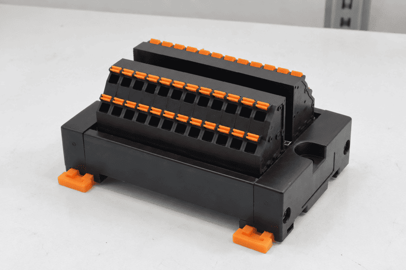
A distribution module can act as a structured wiring hub. It can distribute power, route PLC I/O signals, or split connections from one side to several devices.
For example:
This type of module is useful for machine builders that need a repeatable wiring structure across equipment.
| Scenario | Why a distribution module helps |
|---|---|
| Sensor wiring | Groups multiple sensor connections into one cabinet interface |
| Actuator wiring | Routes outputs to valves, lamps, or field devices |
| PLC cabinet assembly | Reduces point-to-point wiring complexity |
| Machine modules | Supports repeatable plug-and-play wiring |
| AGV or robotics equipment | Helps manage compact wiring routes |
| OEM equipment | Allows custom connector and terminal layouts |
| Field maintenance | Makes replacement and troubleshooting easier |
At NITAI, we can discuss external PLC interface modules, relay modules, and distribution modules based on the customer's wiring plan.
Typical customizable details may include:
Electrical requirements should be confirmed with a qualified engineer. Current capacity, insulation, connector rating, wire size, temperature range, and installation environment must match the application.11
The value of a distribution module is also communication clarity. A request such as “custom PLC distribution module, 2 inputs and 8 outputs, M12 connectors on the field side, terminal blocks on the cabinet side” gives the supplier enough information to discuss design, drawings, samples, and quotation.
That is much clearer than simply saying, “We need a PLC module.”
A module in PLC sourcing project should include document verification before samples or bulk orders. Photos alone cannot confirm the wiring path, terminal size, pin definition, or electrical rating.12
Buyers should verify datasheets, wiring diagrams, pin assignments, mechanical drawings, terminal specifications, electrical ratings, material information, test reports, and certification documents when applicable.
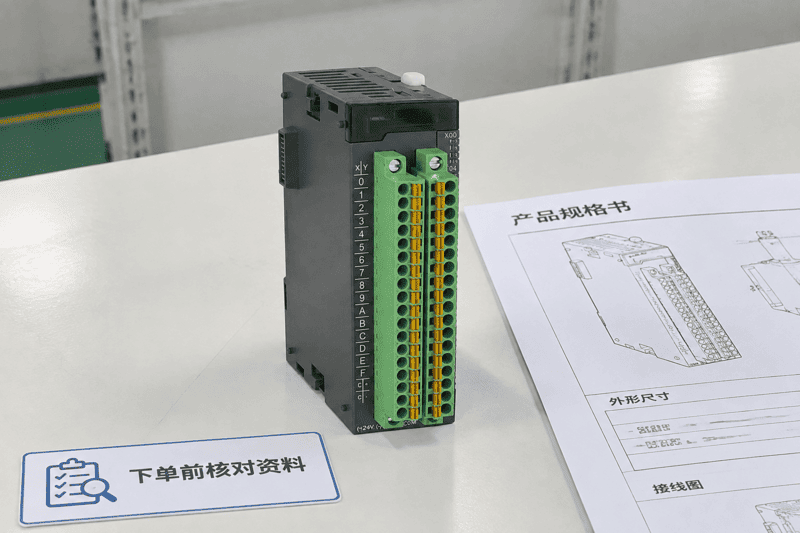
Important documents include:
For custom modules, drawing approval is especially important. Incorrect pin assignments, terminal direction, or connector positions can cause problems across an entire production batch.
A sample is a verification tool. Whenever possible, buyers should test samples under real assembly conditions.
A basic sample review can include:
A correct sample can become a stable standard part for repeated machines and reduce mass-production rework.
For PLC interface modules, relay modules, distribution modules, and wiring harnesses, buyers should also evaluate engineering support.
Good supplier evaluation questions include:
At NITAI, our role is to support industrial connection solutions around automation equipment and control cabinets, including terminal blocks, M8/M12/M16/M23 waterproof circular connectors, PLC interface modules, relay modules, distribution modules, and industrial wiring harnesses. The better starting point is always the real wiring need, not only the module name.
No. A PLC module usually refers to an internal part of the PLC system, such as an I/O or communication module. A PLC interface module is usually an external wiring product that connects PLC signals to terminals, relays, cables, or field devices.
Yes. Many distribution or splitter-style modules can be designed with selected input and output quantities, depending on the electrical requirements and housing structure. Buyers should provide wiring diagrams, current requirements, connector types, and mounting needs before requesting samples.
Include the application, signal type, voltage, current, channel count, wiring diagram, terminal or connector style, mounting method, cable requirements, quantity, certification needs, and target delivery schedule. If the module connects to a PLC brand product, include the relevant datasheet.
Relay modules can help isolate or switch loads outside the PLC output, but they are not a universal protection solution. The design may also require fuses, surge suppression, proper contact ratings, or other protection. Buyers should confirm the design with qualified electrical engineers.
NITAI mainly supports external industrial connection solutions, such as PLC interface modules, relay modules, distribution modules, terminal blocks, circular connectors, and wiring harnesses. These products help connect and organize PLC-related wiring in cabinets and machines. Internal PLC compatibility should be verified through official PLC datasheets.
A module in PLC can mean different things, so buyers should clarify the category before sourcing. Internal PLC modules support the PLC system, while external PLC interface, relay, and distribution modules support wiring, signal routing, field device connection, and cabinet assembly.
If your project needs a PLC distribution module, splitter module, relay interface, or customized wiring solution, NITAI can support connection requirements, samples, drawings, and OEM/ODM development.
"Programmable logic controller", https://en.wikipedia.org/wiki/Programmable_logic_controller. IEC 61131-oriented references describe programmable controllers as systems composed of functional hardware elements, including processing, input/output, communication, and power-related units; this supports the article’s broad use of “module” for PLC-system functional units, although the exact phrase “module in PLC” may not be defined as a formal standard term. Evidence role: definition; source type: institution. Supports: A recognized PLC reference should support that PLC systems are built from functional hardware units such as processors, I/O, power, and communication components.. Scope note: Contextual support for terminology rather than a direct definition of the article’s exact phrase. ↩
"Programmable logic controller", https://en.wikipedia.org/wiki/Programmable_logic_controller. Educational PLC hardware references commonly describe programmable controllers as including a processor or CPU, power supply, input/output modules, and communication interfaces, supporting the article’s list of typical internal PLC module categories. Evidence role: general_support; source type: education. Supports: A university or textbook-style PLC hardware source should list typical PLC components and module categories.. ↩
"PLC Backplane Communication Buses and Protocols Guide", https://industrialmonitordirect.com/blogs/knowledgebase/plc-backplane-protocols-electrical-layers-and-communication-architectures?srsltid=AU7gw4WdQzZQQZ5b1fwneyp4U-GJcAq_PUDTykAqeZf8Iyia0tZhmlOk. Technical descriptions of modular PLC architecture explain that expansion and I/O modules communicate through defined rack, backplane, or bus interfaces, supporting the need to verify compatibility with the specific PLC family and expansion method. Evidence role: mechanism; source type: education. Supports: A technical education source should explain that modular PLC I/O and expansion units connect through a defined rack, backplane, or bus architecture.. ↩
"0-10V vs 4-20mA: Selecting the Right Analog Signal", https://industrialmonitordirect.com/blogs/knowledgebase/0-10v-vs-4-20ma-industrial-analog-signal-selection-guide?srsltid=AU7gw4VAGcqTmepX3Sl1HDGwLRYdxPThViw6cEJYCc0jQ8-wHLkDSR_l. Industrial instrumentation references and IEC signal-standard discussions identify 4–20 mA current loops and 0–10 V voltage signals as established analog control and measurement ranges, supporting their use as examples for PLC analog input channels. Evidence role: definition; source type: institution. Supports: A standards or educational source should support that 4–20 mA current loops and 0–10 V voltage signals are established analog signaling methods in industrial control.. ↩
"Interface terminals in your control panel : r/PLC", https://www.reddit.com/r/PLC/comments/13dqg0b/interface_terminals_in_your_control_panel/. Industrial control wiring references describe PLC input and output circuits as being routed through terminal blocks, interposing relays, cables, and cabinet wiring before reaching sensors or actuators, supporting the article’s description of external PLC interface modules as part of the connection layer. Evidence role: general_support; source type: education. Supports: A neutral automation wiring source should support that PLC I/O signals are commonly connected to field devices through terminal blocks, relays, cables, and cabinet interface hardware.. Scope note: Contextual support for the function of interface wiring; the source may discuss wiring practices rather than the exact product term “PLC interface module.” ↩
"Modular automation toolkit revolutionizes control cabinet ...", https://www.beckhoff.com/en-us/company/news/modular-automation-toolkit-revolutionizes-control-cabinet-design.html. Research and technical literature on modular control-panel wiring describe interface and terminal systems as methods for organizing connections and reducing point-to-point wiring complexity, supporting the article’s claim that external interface modules can simplify PLC-to-field wiring; such sources may not quantify how common the practice is across all industries. Evidence role: general_support; source type: research. Supports: A neutral source should support that modular wiring and interface hardware can reduce point-to-point wiring complexity in control panels.. Scope note: Contextual support for wiring simplification, not a direct market-prevalence statistic. ↩
"1910.332 - Training", http://www.osha.gov/laws-regs/regulations/standardnumber/1910/1910.332. Electrical-safety regulations and guidance define qualified persons as those with training to recognize and avoid electrical hazards, and they require equipment to be used within its ratings and instructions, supporting the article’s statement that safety, load-protection, and compliance decisions require qualified engineering review and datasheet verification. Evidence role: expert_consensus; source type: government. Supports: A government or safety-standard source should support that electrical work and safety decisions require qualified persons and adherence to equipment ratings or instructions.. ↩
"How PLC Relay Outputs Achieve Galvanic Isolation", https://industrialmonitordirect.com/blogs/knowledgebase/galvanic-isolation-in-plc-relay-outputs-explained?srsltid=AU7gw4VbGhqagqlXzx1HWUmPKBp9sFCBXy-h3csNFRbOVEX1F-0OvrqE. Educational materials on PLC output circuits describe interposing relays as devices used to isolate control electronics and switch loads whose voltage or current requirements exceed the direct rating of a PLC output, supporting the article’s stated use cases for relay interfaces. Evidence role: mechanism; source type: education. Supports: A PLC wiring or electrical-controls source should explain that interposing relays can isolate PLC outputs and switch loads beyond the PLC output rating.. ↩
"Do you guys use surge suppressors on Relay Output ...", https://www.reddit.com/r/PLC/comments/1l03r2v/do_you_guys_use_surge_suppressors_on_relay_output/. PLC output-circuit references explain that loads within an output module’s voltage and current ratings may be driven directly, while other loads can require interposing relays, solid-state switching, fusing, or surge suppression, supporting the article’s design-dependent qualification. Evidence role: mechanism; source type: education. Supports: A technical source should support that PLC outputs may directly drive loads within their rating, while inductive or higher-power loads may require relays, fusing, or surge suppression.. ↩
"Sensor actuator boxes", https://www.weidmuller.com/en/products/connectivity/distribution_boxes/signal_distribution_boxes/index.jsp. Standards-based discussions of industrial connector systems, including M8 and M12 sensor/actuator connection formats, support the use of distribution hardware for routing multiple signal and power connections in machine and cabinet wiring; the support is for the wiring function rather than for any specific commercial module design. Evidence role: general_support; source type: institution. Supports: A standards or institutional source should support that industrial connector and distribution systems are used to route sensor, actuator, signal, and power connections.. Scope note: Contextual support for distribution wiring practices, not direct proof of every possible splitter-module configuration. ↩
"1926.405 - Wiring methods, components, and equipment ...", http://www.osha.gov/laws-regs/regulations/standardnumber/1926/1926.405. Electrical machinery and control-panel standards require conductors and components to be selected according to rated current, insulation characteristics, temperature limits, and environmental conditions, supporting the article’s statement that these parameters must match the application. Evidence role: general_support; source type: institution. Supports: An electrical machinery or control-panel standard should support that conductors and components must be selected according to current, insulation, temperature, and environmental ratings.. ↩
"UL 508A Standards Guide for Industrial Control Panels", https://deltawye.com/ul-508a-standards-for-control-panels/. Industrial control-panel and machinery electrical standards identify wiring diagrams, component ratings, and technical documentation as necessary information for verification and maintenance, supporting the article’s warning that photographs alone cannot establish wiring paths, pin definitions, terminal sizes, or electrical ratings. Evidence role: general_support; source type: institution. Supports: A control-panel or machinery electrical standard should support the need for wiring diagrams, component ratings, and technical documentation.. ↩
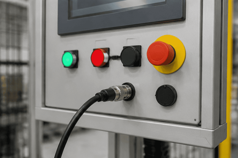
An M12 male connector 5-pin B-coded may look like a straightforward line item, but its name does not…
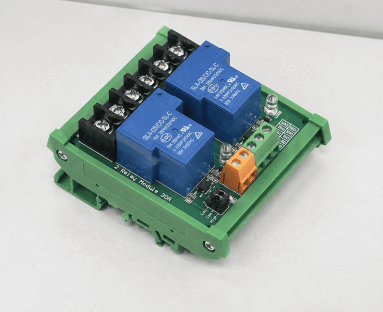
5V relay modules are used to let a low-voltage controller switch a separate electrical circuit, but many buyers…
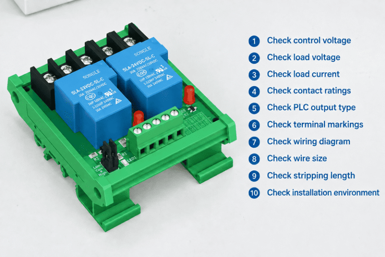
A relay module looks simple until a control cabinet fault appears after commissioning. One wrong assumption about COM,…
NITAI manufactures terminal blocks, M8/M12 waterproof connectors and industrial distribution modules for global OEMs, distributors and automation customers.
Leave a Reply